
MIPS Processor Design Steps with DataPath and Control Implementation
E N D
Presentation Transcript
Amirkabir University of TechnologyComputer Engineering & Information Technology Department پردازنده MIPS معماری & کتاب Patterson & Henessi
مراحل طراحی یک پردازنده • با آنالیز مجموعه دستورات نیازمندیهای DataPath را مشخص میکنیم • اجزا DataPath و روش Clocking را انتخاب میکنیم • اجزا DataPath را در کنار هم قرار میدهیم • با آنالیز هر دستورالعمل نقاط کنترلی را که مسیر داده را تحت تاثیر قرار میدهند را مشخص میکنیم • منطق Control را پیاده سازی میکنیم
بلوک دیاگرام کلی 32 32 32
اجزای اصلی پردازنده 32 32 32
Data Path & Control path • Data path مسیری است که مشخص میکند داده ها چگونه بین پردازنده و سایر المانهای اصلی رد و بدل میشود. اجزای آن عبارتند از: • combinational elements • state (sequential) elements • Control path مشخص میکند که سیگنالهای کنترلی و زمانبندی چگونه به المانهای Data Path میرسد.
مراحل لازم برای اجرای دستور • واکشی دستور از محلی که PC اشاره میکند • خواندن محتوی 0 و یا 1 ویا 2 رجیستر بنا به فیلدهای مشخص شده در دستور • انجام محاسبات ALU همه دستورات بنوعی به ALU نیاز دارند: • دستورات انتقال داداه: برای محاسبه آدرس • دستورات محاسباتی: برای انجام محاسبه • دستورات انشعاب: برای محاسبه آدرس موثر
تفاوت در اجرای دستورات • دستورات انتقال داده • load: access memory for read data {ld R1, 0(R2)} • store: access memory for write data {ld 0(R2), R1} • دستورات ALU • no memory access for operands • access a register for write of result {add R1,R2, R3} • دستورات انشعاب • change PC content based on comparison {bnez R1, Loop}
معماری چندمرحله ای: Multi Sateged • اجرای دستورات در MIPS طی مراحل زیر انجام میشود:
اجزای Data Path • حداقل اجزای Data Path باید شامل المانهای ترکیبی و ترتیبی باشد که بتواند عملیات زیر را اجرا نماید. • Fetch instructions and data from memory • Decode instructions and dispatch them to the execution unit • Execute arithmetic & logic operations • Update state elements (registers and memory)
64 32 32 5 5 5 رجیستر فایل • رجیسترهای 32 گانه پردازنده در ساختاری به اسم رجیستر فایل نگهداری میشوند. • هر یک از رجیسترها را میتوان با مشخص کردن شماره آن خواند و یا نوشت. • Register File’s I/O structure • 3 inputs derived from current instruction to specify register operands (2 for read and 1 for write) • 1 input to write data into a register • 2 outputs carrying contents of the specified registers Read data 1 Read data 2 Read reg 1 Read reg 2 Write reg Write data Register numbers Data Registers RegWrite • Register file’s outputs are always • available on the output lines • Register write is controlled by • RegWrite lead
مدارات ترکیبی combinational logic n n input output • Output determined entirely by input • Contains no storage element
M U X 2n 1 n 32 zero 32 ALU result 32 3 سایر مدارات • Multiplexor selects one out of 2n inputs • ALU performs arithmetic & logic operations • AND: 000 • OR: 001 • add: 010 • subtract: 110 • set on less than: 111 • other 3 combinations unused
write State Element input output storage clock اجزای ترتیبی • State element has storage (i.e., memory) • State defined by storage content • Output depends on input and the state • Write lead controls storage update • Clock lead determines time of update • Examples: main memory, registers, PC
روش اعمال کلاک • Needed to prevent simultaneous read/write to state elements • Edge-triggered methodology: • state elements updated at rising clock edge Combinational logic State element 1 State element 2 clock input
Combinational logic State element 1 ورودی خروجی اجزا • Combinational elements take input from one state element at clock edge and output to another state element at the next clock edge, • Within a clock cycle, state elements are not updated and their stable state is available as input to combinational elements, • Output can be derived from a state element at the edge of one cycle and input into the same state at the next.
PC ALU ALU Datapath Schematic Data Registers Instruction Memory Register # Address Address Register # Instruction Data Memory Register # Data
Read address 4 Instruction PC ALU Instruction Memory Adder 32 Datapath Building Blocks: واکشی دستورات • محتوی PC توسط یک جمع کننده با 4 جمع میشود تا آدرس دستور بعدی محاسبه شود. • مقدار PC به حافظه داده میشود تا دستور واکشی شده و به سایر اجزای Data Path ارسال شود • فرض میشودکه دستورو داده در دو حافظه مجزا نگهداری میشوند. ( بعدا به دلایل آن اشاره خواهد شد)
Read Addr 1 Read Data 1 Register File Control Unit Read Addr 2 Write Addr Read Data 2 Write Data Instruction Datapath Building Blocks: دیکد دستورات • باید مقدار opcode و سایر فیلدهای لازم دستور به واحد کنترل فرستاده شوند. • رجیسترهای لازم هم از رجیستر فایل خوانده شوند.
ALUop 6 5 5 5 5 6 opcode rs rt rd shamt func Read data 1 Read data 2 Instruction Read reg 1 Read reg 2 Write reg Write data R-Type Format zero Register File 5 5 5 ALU ALU RegWrite Datapath Building Blocks: R-Type Instruction • برای دستورات محاسباتی و منطقی که توسط این فرمت نشان داده میشوند لازم است تا دو رجیستر از رجیستر فایل خوانده شده و داده آنها به ALU منتقل شود. • عمل ALU بر اساس نوع دستور تعیین شده و بر روی محتوی رجیسترها انجام میشود. • نتیجه در رجیستر مقصد نوشته میشود. • سیگناهای کنترلی باید ایجاد شود تا نتیجه در لبه کلاک در رجیستر مقصد نوشته شود. همچنین سیگنال ALUop باید تولید شود تا عمل ALU را تعیین کند.
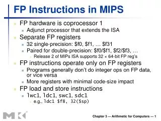
6 5 5 16 opcode rs rt immediate I-Type I-Type Instruction: load/store • برای محاسبه آدرس باید مقدار افست 16 بیتی موجود در دستورالعمل بصورت یک عدد علامت دار 32 بیتی تبدیل شده وبا مقدار پایه موجود در rs جمع شود. LW R2, 232(R1) SW R5, -88(R4) 16 32 sign extend
I-Type Instruction: load/store بنابراین اجرای این دستور با اجزای زیر درارتباط خواهد بود: • Register file • برای دسترسی به رجیستر پایه و رجیستر مقصد • Sign extender • برای تبدیل آدرس • ALU • برای جمع کردن آدرس پایه و مقدار افست توسعه داده شده • Data memory to load/store data • مقادیر آدرس، و داده ورودی یاخروجی باید به حافظه فرستاده شوند • سیگناهای کنترلی MemRead, MemWrite, Clock باید به حافظه فرستاده شوند
6 5 5 16 ALUop opcode rs rt immediate I-Type MemWrite Read data 1 Read data 2 zero Instruction Read reg 1 Read reg 2 Write reg Write data ALU ALU 5 Read data Address Registers 5 5 Data Memory Write data RegWrite sign extend 32 MemRead 16 Datapath Building Blocks: load/store
6 5 5 16 opcode rs rt immediate I-Type 16 sign extend 32 shift left 2 32 ALU Adder PC+4 I-Type Instruction: bne • مقصد دستور انشعاب از جمع مقدار افست با PC بدست می آید. از آنجائیکه این مقصد باید مضربی از 4باشد، نیاز است تا مقدار افست به اندازه 2 بار به سمت چپ شیفت داده شود. • if Reg[rs] != Reg[rd], • PCcurrent=(PCprevious+4) + Imm<< 2 • else if Reg[rs] == Reg[rt] • PCcurrent=(PCprevious+4) bne R1, R2, Imm
I-Type Instruction: bne • برای مقایسه رجیسترهای دستور bne از ALU استفاده میشود. از اینرو نتیجه این مقایسه با سیگنال Zero که در خروجی ALU تعبیه شده است مشخص میگردد. • بعلت درگیر بودن ALU برای محاسبه آدرس مقصد از یک جمع کننده دیگر استفاده میشود.
6 5 5 16 opcode rs rt immediate I-Type 5 5 ALU Adder Datapath Building Blocks: bne ALUop = subtract Read data 1 Read data 2 zero To branch control logic Instruction Read reg 1 Read reg 2 Write reg Write data ALU ALU Registers RegWrite sign extend 32 shift left 2 16 Branch target PC+4 from Instruction Datapath
Branch target address Add Add 4 Shift left 2 ALU control PC zero (to branch control logic) Read Addr 1 Read Data 1 Register File Read Addr 2 Instruction ALU Write Addr Read Data 2 Write Data Sign Extend 16 32 Datapath Building Blocks: bne
Add 4 4 Jump address Instruction Memory Shift left 2 28 Read Address PC Instruction 26 Datapath Building Blocks: jump instruction • اجرای دستور jump از طریق المانهای زیر انجام میشود: • 26 بیت مقدار موجود در دستورالعمل به اندازه 2 بیت به سمت چپ شیفت داده شده و با 28 بیت کم ارزشPC جایگزین میشود.
ساخت یک Data Path واحد بااجزای فوق • اجزای مورد نیاز برای قسمت های مختلف در کنار هم قرار داده شده و سیگناهای کنترلی و مالتی پلکسرهای مورد نیاز به آن افزوده میشوند. • در طراحی Single Cycle همه مراحل واکشی، دیکد و اجرا در یک کلاک انجام میشود! • زمان این کلاک برابر خواهد بود با زمان لازم برای طی کردن طولانی ترین مسیر که میتواند زمان زیادی باشد. • علاوه برآن امکان به اشتراک گذاشتن سخت افزار برای عملیات یکسان وجود ندارد.
Add RegWrite ALUSrc ALU control MemWrite MemtoReg 4 ovf zero Read Addr 1 Instruction Memory Read Data 1 Address Register File Read Addr 2 Data Memory Read Address PC Instruction Read Data ALU Write Addr Read Data 2 Write Data Write Data MemRead Sign Extend 16 32 Fetch, R, and Memory Access Portions
31 25 20 15 10 5 0 R-type: op rs rt rd shamt funct 31 25 20 15 0 I-Type: address offset op rs rt 31 25 0 J-type: op target address افزودن واحد کنترل • این واحد باید : • عملیاتAlu را مشخص نماید، سیگناهای رجیستر فایل و حافظه را تولید نماید، جریان داده از طریق مالتی پلکسرها را کنترل نماید. ملاحظات • مقدار اپکد همیشه در بیت های 31-26 قراردارد • آدرس رجیسترهائی که باید خوانده شوند توسط فیلد rs (بیت های 25-21 وفیلد rt (بیت های 16-20)مشخص میشوند. • آدرس رجیستریکه بایدنوشته شونددریکیاز دو مکان زیر است: فیلد rt برای دستور lw و فیلد rd برای دستوراتR-Type • مقدار افست در بیت های 0-15 است.
Single Cycle Datapath with Control Unit 0 Add Add 1 4 Shift left 2 PCSrc ALUOp Branch MemRead Instr[31-26] Control Unit MemtoReg MemWrite ALUSrc RegWrite RegDst ovf Instr[25-21] Read Addr 1 Instruction Memory Read Data 1 Address Register File Instr[20-16] zero Read Addr 2 Data Memory Read Address PC Instr[31-0] 0 Read Data 1 ALU Write Addr Read Data 2 0 1 Write Data 0 Instr[15 -11] Write Data 1 Instr[15-0] Sign Extend ALU control 16 32 Instr[5-0]
R-type Instruction Data/Control Flow 0 Add Add 1 4 Shift left 2 PCSrc ALUOp Branch MemRead Instr[31-26] Control Unit MemtoReg MemWrite ALUSrc RegWrite RegDst ovf Instr[25-21] Read Addr 1 Instruction Memory Read Data 1 Address Register File Instr[20-16] zero Read Addr 2 Data Memory Read Address PC Instr[31-0] 0 Read Data 1 ALU Write Addr Read Data 2 0 1 Write Data 0 Instr[15 -11] Write Data 1 Instr[15-0] Sign Extend ALU control 16 32 Instr[5-0]
Load Word Instruction Data/Control Flow 0 Add Add 1 4 Shift left 2 PCSrc ALUOp Branch MemRead Instr[31-26] Control Unit MemtoReg MemWrite ALUSrc RegWrite RegDst ovf Instr[25-21] Read Addr 1 Instruction Memory Read Data 1 Address Register File Instr[20-16] zero Read Addr 2 Data Memory Read Address PC Instr[31-0] 0 Read Data 1 ALU Write Addr Read Data 2 0 1 Write Data 0 Instr[15 -11] Write Data 1 Instr[15-0] Sign Extend ALU control 16 32 Instr[5-0]
Branch Instruction Data/Control Flow 0 Add Add 1 4 Shift left 2 PCSrc ALUOp Branch MemRead Instr[31-26] Control Unit MemtoReg MemWrite ALUSrc RegWrite RegDst ovf Instr[25-21] Read Addr 1 Instruction Memory Read Data 1 Address Register File Instr[20-16] zero Read Addr 2 Data Memory Read Address PC Instr[31-0] 0 Read Data 1 ALU Write Addr Read Data 2 0 1 Write Data 0 Instr[15 -11] Write Data 1 Instr[15-0] Sign Extend ALU control 16 32 Instr[5-0]
Adding the Jump Operation Instr[25-0] 1 Shift left 2 28 32 26 0 PC+4[31-28] 0 Add Add 1 4 Shift left 2 PCSrc Jump ALUOp Branch MemRead Instr[31-26] Control Unit MemtoReg MemWrite ALUSrc RegWrite RegDst ovf Instr[25-21] Read Addr 1 Instruction Memory Read Data 1 Address Register File Instr[20-16] zero Read Addr 2 Data Memory Read Address PC Instr[31-0] 0 Read Data 1 ALU Write Addr Read Data 2 0 1 Write Data 0 Instr[15 -11] Write Data 1 Instr[15-0] Sign Extend ALU control 16 32 Instr[5-0]
Cycle 1 Cycle 2 Clk lw sw Waste مزایا و معایب معماری Single Cycle • زمان کلاک بطور موثر استفاده نمیشود زیرا بر اساس طولانی ترین دستور تنظیم شده است. این امر در صورت داشتن دستورات پیچیده مثل دستورات اعشاری میتواند خیلی وخیم باشد. • فضای بیشتری در روی چیپ لازم دارد زیرا تعداد بیشتری از المانهای سخت افزاری لازم دارد. • ساده و قابل فهم است.
محاسبه طولانی ترین دستورالعمل • طول کلاک باید بر اساس زمان لازم برای طولانی ترین دستور طراحی شود. 600 ps
نگرش Multicycle Datapath • هر دستور به تعدادی مرحله کوچکتر تقسیم شده و هر یک از این مراحل در یک کلاک اجرا میشوند. بدین ترتیب برای اجرای هر دستور به تعدادی کلاک کوچک تر نیاز خواهیم داشت. • مراحل طوری انتخاب میشوند که کار انجام گرفته در آنها متعادل باشد. • در هر مرحله فقط از یکی از بلوک های سخت افزاری اصلی استفاده میشود. • هر دستور تعداد متفاوتی کلاک لازم دارد. • فقط به یک حافظه نیاز دارد. البته در هر سیکل فقط میتوان یکبار به حافظه دسترسی داشت. • فقط به یک ALU/adder نیاز دارد. البته در هر سیکل بیش از یکبار از ALU نمیتوان استفاده نمود.
IR Address Memory A Read Addr 1 PC Read Data 1 Register File Read Addr 2 Read Data (Instr. or Data) ALUout ALU Write Addr Write Data Read Data 2 B Write Data MDR نگرش Multicycle Datapath • در این معماری مقادیری که در سیکلهای بعدی دستور مورد نیاز هستند در رجیسترهائی ذخیره میشوند. در نتیجه باید اجزای زیر به معماری افزوده شوند: IR – Instruction RegisterMDR – Memory Data Register A, B – regfile read data registersALUout – ALU output register
MDR The Multicycle Datapath with Control Signals PCWriteCond PCWrite PCSource IorD ALUOp MemRead Control ALUSrcB MemWrite ALUSrcA MemtoReg RegWrite IRWrite RegDst PC[31-28] Instr[31-26] Shift left 2 28 Instr[25-0] 2 0 1 Address Memory 0 PC 0 Read Addr 1 A Read Data 1 IR Register File 1 1 zero Read Addr 2 Read Data (Instr. or Data) 0 ALUout ALU Write Addr Write Data 1 Read Data 2 B 0 1 Write Data 4 1 0 2 Instr[15-0] Sign Extend Shift left 2 3 32 ALU control Instr[5-0]
Datapath control points Combinational control logic . . . . . . . . . State Reg Inst Opcode Next State واحد کنترل Multicycle • در معماری Multicycle سیگنالهای کنترل را نمیتوان فقط از روی بیت های دستورالعمل بدست آورد. زیرا اطلاعاتی در مورد سیکلهای دستورالعمل در اپکد آن ذخیره میشود. • از اینرو از یک ماشین FSM برای طراحی واحد کنترل استفاده میشود. • تعدادی state محدود برای پردازنده فرض میشود که در state reg ذخیره میشوند. • state بعدی از روی state فعلی ومقادیر ورودی تعیین میشوند.
IFetch Exec Mem WB مراحل 5 گانه دستور load Cycle 1 Cycle 2 Cycle 3 Cycle 4 Cycle 5 • IFetch: Instruction Fetch and Update PC • Dec: Instruction Decode, Register Read, Sign Extend Offset • Exec: Execute R-type; Calculate Memory Address; Branch Comparison; Branch and Jump Completion • Mem: Memory Read; Memory Write Completion; R-type Completion (RegFile write) • WB: Memory Read Completion (RegFile write) Dec lw
مراحل اجرای دستورات مختلف • اجرای دستورات متفاوت زمانهای مختلفی نیاز دارد. • اجرای دستورات MIPS به 3 تا 5 سیکل نیاز دارند.
اجزای اصلی واحد کنترل بخش مشترک واکشی دیکد و خواندن دستور اجزای مربوط به دستورات S t a r t I n s t r u c t i o n f e t c h / d e c o d e a n d r e g i s t e r f e t c h ( F i g u r e 5 . 3 7 ) M e m o r y a c c e s s R - t y p e i n s t r u c t i o n s B r a n c h i n s t r u c t i o n J u m p i n s t r u c t i o n i n s t r u c t i o n s ( F i g u r e 5 . 3 9 ) ( F i g u r e 5 . 4 0 ) ( F i g u r e 5 . 4 1 ) ( F i g u r e 5 . 3 8 )
بخش مشترک واکشی دیکد و خواندن دستور I n s t r u c t i o n d e c o d e / I n s t r u c t i o n f e t c h R e g i s t e r f e t c h 0 M e m R e a d 1 A L U S r c A = 0 I o r D = 0 A L U S r c A = 0 I R W r i t e S t a r t A L U S r c B = 1 1 A L U S r c B = 0 1 A L U O p = 0 0 A L U O p = 0 0 P C W r i t e P C S o u r c e = 0 0 ) e ) p ' ) y t Q ' - R P E = B p ' M O ( ) = J ' W ' S p ' = = p O O ( ( r p o ) ' W O L ' ( = p O ( M e m o r y r e f e r e n c e F S M R - t y p e F S M B r a n c h F S M J u m p F S M ( F i g u r e 5 . 3 8 ) ( F i g u r e 5 . 3 9 ) ( F i g u r e 5 . 4 0 ) ( F i g u r e 5 . 4 1 )
دسترسی به حافظه محاسبه آدرس ترتیب خواندن از حافظه خواندن از حافظه ذخیره در رجیستر ترتیب نوشتن در حافظه نوشتن در حافظه F r o m s t a t e 1 ( O p = ' L W ' ) o r ( O p = ' S W ' ) M e m o r y a d d r e s s c o m p u t a t i o n 2 A L U S r c A = 1 A L U S r c B = 1 0 A L U O p = 0 0 ( O p ) ' = W ' S L ' W ' = ) p M e m o r y M e m o r y O ( a c c e s s a c c e s s 3 5 M e m R e a d M e m W r i t e I o r D = 1 I o r D = 1 W r i t e - b a c k s t e p 4 T o s t a t e 0 R e g W r i t e ( F i g u r e 5 . 3 7 ) M e m t o R e g = 1 R e g D s t = 0
دستورات R-type اجرای دستورات نوشتن نتیجه در رجیستر F r o m s t a t e 1 ( O p = R - t y p e ) E x e c u t i o n 6 A L U S r c A = 1 A L U S r c B = 0 0 A L U O p = 1 0 R - t y p e c o m p l e t i o n 7 R e g D s t = 1 R e g W r i t e M e m t o R e g = 0 T o s t a t e 0 ( F i g u r e 5 . 3 7 )
دستور Branch در یک مرحله اجرامیشود: اگرشرط درست باشد PC با آدرس دستورانشعاب پر میشود. F r o m s t a t e 1 ( O p = ' B E Q ' ) B r a n c h c o m p l e t i o n 8 A L U S r c A = 1 A L U S r c B = 0 0 A L U O p = 0 1 P C W r i t e C o n d P C S o u r c e = 0 1 T o s t a t e 0 ( F i g u r e 5 . 3 7 )
دستور Jump PC با آدرس محل انشعاب پر میشود. F r o m s t a t e 1 ( O p = ' J ' ) J u m p c o m p l e t i o n 9 P C W r i t e P C S o u r c e = 1 0 T o s t a t e 0 ( F i g u r e 5 . 3 7 )