Download
1 / 32
320 likes | 344 Views
Explore examples and concepts related to electromagnetic induction, transformers, power loss, and efficiency. Learn how coils, flux, and voltage affect electrical systems.

E N D
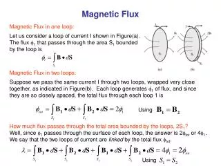
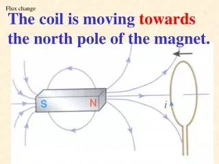
Flux change The coil is moving towards the north pole of the magnet.
Class example S S
Alternator I X Note that there is no power supply!
Dynamo I - +
Y-gain = 50 mV cm-1 Time base = 50 ms cm-1
Transformer I Power station Step-up transformer Step-down transformer V Consumer P = power input from power station V = voltage after stepping up I = current flowing through the cable
We have the followings: • P is fixed • As V is large, I becomes small • Heat loss in the cable = 2 power loss in the cable becomes smaller
Class example(P.241#7) • Total resistance of cable • = 0.165 10 2 • = 3.3 (b) Voltage drop along the line = I R = 400 3.3 = 1320 V
(c) Power input to the line = V I = 132000 400 = 52800000 W = 52.8 MW
(d) Power lost in the line = I2 R = 4002 3.3 = 528000W = 0.528 MW
(e) The ‘lost’ energy is changed into internal energy in the cable and then changed into heat energy in the environment.
(f) The primary coil should have larger number of turns. The number of turns in primary coil is 550 times of that of the secondary coil.
(g) By P = V I 1440000 = 240 IS IS = 600 A (h) The machines and electrical appliances used in factories and homes are not .
(h) The machines and electrical appliances used in factories and homes are not designed to be operated at such a high voltage and hence it is very dangerous.
92CEII#35 Which of the following can increase the efficiency of a transformer? (1) Increasing the number of turns of the secondary coil. (2) Using a laminated iron core. (3) Using thicker copper wires to make the coils .
94CEII#34 100 kW of electrical power is transmitted at 20 kV through cables of total resistance 4 . Find the potential drop and power loss in the cables. By P = V I I = 100k 20k = 5 A Potential drop in cables = I R = 5 (4) = 20 V Power loss in cables = V I = 20 (5) = 100 W Power loss in cables = I2 R = 52 (4) = 100 W
96CEII#31 Which of the following devices is not an application of electromagnetic induction? A a transformer B a bicycle dynamo C a magnetic tape playback head D a moving coil loudspeaker
Class example(P.244#13) (a) i. Resistance = ii.current through the lamp = 2 A iii.Power loss: