Download
1 / 29
290 likes | 482 Views
Simulations and Diagnostics for the Front End Test Stand. Simon Jolly Imperial College 18 th April 2007. From HPPA’s to FETS (D. Findlay). New generation of High Power Proton Accelerators (HPPAs) required for: neutron spallation sources neutrino factories Transmutation facilities

E N D
Simulations and Diagnostics for the Front End Test Stand Simon Jolly Imperial College 18th April 2007
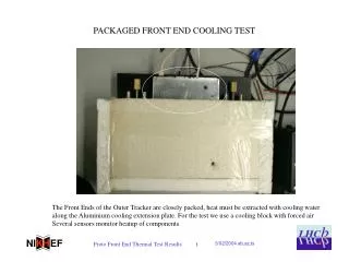
From HPPA’s to FETS (D. Findlay) • New generation of High Power Proton Accelerators (HPPAs) required for: • neutron spallation sources • neutrino factories • Transmutation facilities • Accelerator driven power reactor systems • Tritium production • High power is difficult: • Imperative to keep beam losses low (~1 W/m) • ISIS only ~0.2 MW, but ×2 beam losses would make life very difficult (2–3 mSv annual dose limit) • Need good quality beam • Space charge issues significant • Implies beam chopper necessary even if no rings involved • Need to control transients — RF and target issues • Implies beam chopper very desirable • “The Front End Test Stand (FETS) is intended to demonstrate the early stages of acceleration (0-3MeV) and beam chopping required for HPPA’s”
FETS Specification (A. Letchford) • 60 mA H- ion source • 65 keV 3 solenoid magnetic LEBT • 324 MHz, 3 MeV RFQ • High speed beam chopper & MEBT • Conventional and non-destructive diagnostics • Up to 2 ms pulse length • Up to 50 pps rep. rate • ‘Perfect’ chopping
FETS Layout FETS main components: • High brightness H- ion source. • Magnetic Low Energy Beam Transport (LEBT). • High current/duty factor Radio Frequency Quadrupole (RFQ). • Very high speed beam chopper. • Comprehensive diagnostics. Chopper RFQ
Solenoids RFQ 0.21 T 0.05 T 0.25 T d1 d2 d4 d3 25 cm 30 cm 19 cm 30 cm 24 cm 30 cm 15 cm H– Drift areas (vacuum) LEBT Design • Low Energy Beam Transport takes beam from ion source and focuses into RFQ. • Design based on ISIS LEBT - three solenoids between drift areas. • Optimise design using GPT simulations of beam envelope and profile along LEBT. • Constraints: • B < 0.6 T, solenoids long enough to ensure flat axial field (d ≥ 25cm). • d1 = 25cm, d4 = 15cm (minimum for vacuum equipment and diagnostics). • Overall length must not be too long (cost). • RFQ acceptance: 2-3mm, 50-60mrad (from ~20mm, withex/y = 0.3pmm-mrad).
LEBT Solenoid Focussing • “Hard” focussing leads to large emittance growth. • “Soft” focussing, with 2 strong and 1 weak solenoid, give better results. Hard focussing Soft focussing
LEBT Solenoid Focussing (2) • Solenoid focussing solutions very sensitive to input conditions: very little data to go on! • “Optimised” LEBT produces very different results when using real ion source measurements. • Initially only 2 sources of data for GPT beam conditions (which look very different…): • Ion source emittance measurements. • MAFIA simulations of ion source output. • No information on X-Y profile or space charge…
LEBT Simulation: Trajectories Beam Z-X trajectories using optimised Weak Focussing Solution, but measured parameters: beam only shrinks from Rmax=25mm to Rmax=15mm…
Ion Source Emittance Data X • Measured ion source emittance data gives emittance ~600mm from ion source exit: • Hrms = 0.92, Vrms = 1.01 mm mrad. • xrms = 26.0 mm, x’rms = 32.0 mrad. • yrms = 24.6 mm, y’rms = 35.0 mrad. • MAFIA simulations give emittance at exit of ion source cold box. • Using GPT to try and match one to the other totally hopeless… X Y Y
Space Charge Simulations in GPT • Treat set as mono-energetic 2D slice at 600mm, input to GPT and track backwards using 2D space charge model and levels of space charge compensation. • Try to match X-Y profile at 0mm to real exit aperture of cold box and results from MAFIA simulations, using different space charge compensation and time-reversed simulation. • Various Space Charge models tested for consistency (2D and 3D).
Results: Input Data (Emit) Emittance plots for “initial” beam data X Y
Results: Emittance, 10% SC Emittance plots for beam at 0mm, 10% space charge X Y
Results: Emittance, 30% SC Emittance plots for beam at 0mm, 30% space charge X Y
Results: Emittance, 50% SC Emittance plots for beam at 0mm, 50% space charge X Y
The Pepperpot Emittance Scanner • Current Allison-type scanners give high resolution emittance measurements, but at fixed z-position and too far from ion source. • X and Y emittance also uncorrelated, with no idea of x-y profile. • Correlated, 4-D profile (x, y, x’, y’) required for accurate simulations. • Pepperpot reduces resolution to make correlated 4-D measurement. • Moving stage allows measurement at different z-locations: space charge information. • Added bonus: make high resolution x-y profile measurements
Pepperpot Principle • Beam segmented by tungsten screen. • Beamlets drift ~10mm before producing image on quartz screen. • Copper block prevents beamlets from overlapping and provides cooling. • CCD camera records image of light spots. • Calculate emittance from spot distribution. Quartz screen Copper block Fast CCD Camera H- Ion Beam Tungsten screen H- Beamlets
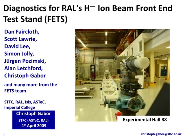
Ion Source Development Rig Emittance scanners Ion source Ion source test facility vacuum tank
Mk.II Pepperpot Design Beam profile head Tungsten mesh Pepperpot head Shutter Bellows Camera Moving rod Vacuum bellows Mounting flange
Pepperpot Results Raw data
Scintillator Measurements 5 kV Ext 5.5 kV Ext 6 kV Ext 6.5 kV Ext 7 kV Ext 8 kV Ext 9 kV Ext 11 kV Ext
Conclusions • Particle dynamics simulations extremely sensitive to input conditions. • Pepperpot finally providing necessary information for 4-D emittance profiles. • Significant aid to ion source development: • Profile measurements. • Multiple emittance measurements. • More results in time for DIPAC’07…
Relevant Experience • Experience with numerous accelerator simulation codes: MAD, DIMAD, LIAR, MatLIAR, Guinea-Pig, GPT (particle dynamics and space charge). • Practical experience with both electron and hadron machines. • Project management for Hilger Crystals: novel x-ray system for afterglow measurement. • Previous work in Medical Physics (Whittington Hospital).
Platform DC Power Supply Platform Ground 35kV Pulsed Extract Power Supply 17kV - + Laboratory Ground 18kV Extraction Electrode, Coldbox and Analysing Magnet all Pulsed - + 35keV H- Beam 53.7mm Post Extraction Acceleration Gap
Scintillator Problems • Pepperpot rapidly became “scintillator destruction rig”. • Scintillator requirements: • Fast (down to 500ns exposure). • High light output. • Survives beam (<1 micron stopping distance). • High energy density from Bragg peak causes severe damage… • Finally settled on Ce-doped quartz.
YAG:Ce Spot Intensity P46 (500ms exposure) P43 (10ms exposure) Ruby (500ms exposure) YAG:Ce (100ms exposure)
Simulated Beam Profile Image width: 100mm Camera res. = 49 microns/pixel Angle res. = 4.88 mrad
Simulated Beam: Emittance Plots ex = 6.01p x-x’ ey = 6.51p y-y’