Download
1 / 12
120 likes | 238 Views
Follow Team 4 as they model a vintage SOLO-1 ARF plane, focusing on lift components, landing gear, front steering, servos, and the Saito FA-40 engine in this detailed project report.

E N D
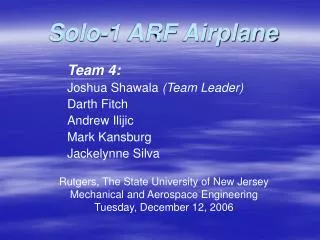
Solo-1 ARF Airplane Team 4: Joshua Shawala (Team Leader) Darth Fitch Andrew Ilijic Mark Kansburg Jackelynne Silva Rutgers, The State University of New Jersey Mechanical and Aerospace Engineering Tuesday, December 12, 2006
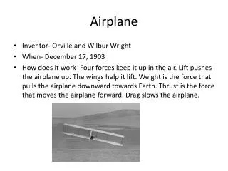
Overview • The focus of this project was to model an existing SOLO-1 ARF (Almost Ready-to Fly) remote control airplane that is approximately fifteen years old. • The aircraft is equipped with a three point fixed landing gear system. • The controls consist of three servos that operate the throttle, elevator, and the rudder/front wheel steering. • The wing has a uniform cross section with a slight rise from tip to tip. Thrust is generated by the Saito FA-40 engine, which consists of many intricate components which work together to power propeller. Team 4
Lift Components • The main wing is fixed to the fuselage by two rubber bands so that unwanted impacts do not result in component damage. • The only movable lift components are the elevator and the rudder, which can direct the pitch and the yaw. • Without independent flaps on each side, there is no way no directly control the roll of the aircraft. Team 4
Lift Components Team 4
Landing Gear The purpose of the landing gear is to support the aircraft, and to allow for motion on land during acceleration for takeoff and deceleration for landing. Impact energy absorption is achieved through deflection of the base plate and the front spring arm. Team 4
Front Steering • The front spring arm is attached to the engine mount, such that static support and impact support of the engine is done with minimal stress on the structure. • The steering arm is bolted to the spring arm and connected to a wire such that a servo can control the wheel angle. Team 4
Servos/Controls Team 4
Servos/Controls • These servos are considerably outdated, since the airplane is around 15 years old. • The servo completes 200 degrees of motion, and the gear ratio is 212.5:1 • All of the input of the operator is transmitted from the remote control to the receiver, which transmits the appropriate signals to the respective servo. Team 4
Saito FA-40 • Engine: 6.6cc single cylinder four stroke • The FA-40 has an output of about .65hp • Safe rpm range is between 2,000 and 12,000 rpm BORE: 22mmSTROKE: 17.4mm Weight:300g Team 4
Engine Team 4
Thanks to: • Ching-Jui Chang (Ray) • Mechanical & Aerospace Engineering Department • The DSV and EIT Labs for providing PRO-E Team 4