EE462L, Spring 2014 Waveforms and Definitions
EE462L, Spring 2014 Waveforms and Definitions. + −. Circuit in a box, two wires. + −. Circuit in a box, three wires. + −. Instantaneous power p(t) flowing into the box. Any wire can be the voltage reference.

EE462L, Spring 2014 Waveforms and Definitions
E N D
Presentation Transcript
+ − Circuit in a box, two wires + − Circuit in a box, three wires + − Instantaneous power p(t) flowing into the box Any wire can be the voltage reference Works for any circuit, as long as all N wires are accounted for. There must be (N – 1) voltage measurements, and (N – 1) current measurements.
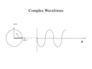
Two-wire sinusoidal case zero average Displacement power factor Average power
compare Root-mean squared value of a periodic waveform with period T Compare to the average power expression The average value of the squared voltage Apply v(t) to a resistor rms is based on a power concept, describing the equivalent voltage that will produce a given average power to a resistor
Root-mean squared value of a periodic waveform with period T For the sinusoidal case
V 0 0 < D < 1 DT T RMS of some common periodic waveforms Duty cycle controller By inspection, this is the average value of the squared waveform
RMS of common periodic waveforms, cont. Sawtooth V 0 T
V 0 V 0 V 0 V 0 V 0 V 0 0 -V RMS of common periodic waveforms, cont. Using the power concept, it is easy to reason that the following waveforms would all produce the same average power to a resistor, and thus their rms values are identical and equal to the previous example
the ripple = + the minimum value 0 RMS of common periodic waveforms, cont. Now, consider a useful example, based upon a waveform that is often seen in DC-DC converter currents. Decompose the waveform into its ripple, plus its minimum value.
RMS of common periodic waveforms, cont. Recognize that
In this example, is defined as the average value of the sawtooth portion RMS of segmented waveforms Consider a modification of the previous example. A constant value exists during D of the cycle, and a sawtooth exists during (1-D) of the cycle. DT (1-D)T
RMS of segmented waveforms, cont. a weighted average So, the squared rms value of a segmented waveform can be computed by finding the squared rms values of each segment, weighting each by its fraction of T, and adding
Practice Problem The periodic waveform shown is applied to a 100Ω resistor. What value of αyields 50W average power to the resistor?
Fourier series for any physically realizable periodic waveform with period T When using arctan, be careful to get the correct quadrant
where the fundamental angle shift is Two interesting properties Half-wave symmetry, Time shift, then no even harmonics (remove the average value from i(t) before making the above test) Thus, harmonic k is shifted by k times the fundamental angle shift
V –V T T/2 Square wave
T/2 V –V T Triangle wave
α = 30º Current Current 0 30 60 90 120 150 180 210 240 270 300 330 360 0 30 60 90 120 150 180 210 240 270 300 330 360 α = 90º Angle Angle Current 0 30 60 90 120 150 180 210 240 270 300 330 360 α = 150º Angle Triac light dimmer waveshapes(bulb voltage and current waveforms are identical)
Fourier coefficients for light dimmer waveform Vp is the peak value of the underlying AC waveform
RMS in terms of Fourier Coefficients which means that and that for any k
Bounds on RMS From the power concept, it is obvious that the rms voltage or current can never be greater than the maximum absolute value of the corresponding v(t) or i(t) From the Fourier concept, it is obvious that the rms voltage or current can never be less than the absolute value of the average of the corresponding v(t) or i(t)
277V fluorescent light (electronic ballast) THDi = 11.6% 240V residential air conditioner THDi = 10.5% Refrigerator THDi = 6.3% 277V fluorescent light (magnetic ballast) THDi = 18.5% Some measured current waveforms
Vacuum cleaner THDi = 25.9% PC THDi = 134% Microwave oven THDi = 31.9% Some measured current waveforms, cont.
200 150 100 50 0 Volts -50 -100 -150 -200 Resulting voltage waveform at the service panel for a room filled with PCs THDV = 5.1% (2.2% of 3rd, 3.9% of 5th, 1.4% of 7th) THDV = 5% considered to be the upper limit before problems are noticed THDV = 10% considered to be terrible
Bad enough to cause many power electronic loads to malfunction Some measured current waveforms, cont. 5000HP, three-phase, motor drive (locomotive-size)
+ − Circuit in a box, two wires + − Circuit in a box, three wires + − Any wire can be the voltage reference Now, back to instantaneous power p(t)
Messy! Average power in terms of Fourier coefficients
Cross products disappear because the product of unlike harmonics are themselves harmonics whose averages are zero over T! Not wanted in an AC system Harmonic power – usually small wrt. P1 Due to the DC Due to the 1st harmonic Due to the 2nd harmonic Due to the 3rd harmonic Average power in terms of Fourier coefficients, cont.
Consider a special case where one single harmonic is superimposed on a fundamental frequency sine wave Combined Fund. freq + Harmonic Using the combined waveform, • Determine the order of the harmonic • Estimate the magnitude of the harmonic • From the above, estimate the RMS value of the waveform, • and the THD of the waveform
Single harmonic case, cont. Determine the order of the harmonic • Count the number of cycles of the harmonic, or the number of peaks of the harmonic 17 T
Single harmonic case, cont. Estimate the magnitude of the harmonic • Estimate the peak-to-peak value of the harmonic where the fundamental is approximately constant Viewed near the peak of the underlying fundamental (where the fundamental is reasonably constant), the peak-to-peak value of the harmonic appears to be about 30 Imagining the underlying fundamental, the peak value of the fundamental appears to be about 100 Thus, the peak value of the harmonic is about 15
Single harmonic case, cont. Estimate the RMS value of the waveform Note – without the harmonic, the rms value would have been 70.7V (almost as large!)
Single harmonic case, cont. Estimate the THD of the waveform
Given single-phase v(t) and i(t) waveforms for a load • Determine their magnitudes and phase angles • Determine the average power • Determine the impedance of the load • Using a series RL or RC equivalent, determine the R and L or C
Determine voltage and current magnitudes and phase angles Voltage sinewave has peak = 100V, phase angle = 0º Current sinewave has peak = 50A, phase angle = -45º Using a sine reference,
The equivalent series impedance is inductive because the current lags the voltage where ω is the radian frequency (2πf) If the current leads the voltage, then the impedance angle is negative, and there is an equivalent capacitance
C’s and L’s operating in periodic steady-state Examine the current passing through a capacitor that is operating in periodic steady state. The governing equation is which leads to Since the capacitor is in periodic steady state, then the voltage at time to is the same as the voltage one period T later, so or The conclusion is that which means that the average current through a capacitor operating in periodic steady state is zero
Now, an inductor Examine the voltage across an inductor that is operating in periodic steady state. The governing equation is which leads to Since the inductor is in periodic steady state, then the voltage at time to is the same as the voltage one period T later, so or The conclusion is that which means that the average voltage across an inductor operating in periodic steady state is zero
KVL and KCL in periodic steady-state Since KVL and KCL apply at any instance, then they must also be valid in averages. Consider KVL, KVL applies in the average sense The same reasoning applies to KCL KCL applies in the average sense
KVL and KCL in the average sense Consider the circuit shown that has a constant duty cycle switch + VSavg− + VRavg− 0 A R1 Iavg + VLavg = 0 − L R2 V Iavg A DC multimeter (i.e., averaging) would show and would show V = VSavg + VRavg
KVL and KCL in the average sense, cont. Consider the circuit shown that has a constant duty cycle switch + VSavg− + VRavg− R1 Iavg Iavg + VCavg − C R2 V 0 A DC multimeter (i.e., averaging) would show and would show V = VSavg + VRavg + VCavg
i i in d + – V V i i L C in out C L – + I out Practice Problem