Download
1 / 15
150 likes | 276 Views
This chapter delves into the qualitative analysis of non-ideal diode behavior, focusing on key phenomena such as reverse-bias breakdown, including avalanching and the Zener process. It discusses high-current phenomena that occur as the applied voltage approaches the built-in potential (Vbi) and the impact of series resistance and high-level injection on I-V characteristics. Detailed insights into the G-R current in both reverse and forward bias conditions are provided, along with empirical data comparing ideal and commercial silicon diode performance at 300K.

E N D
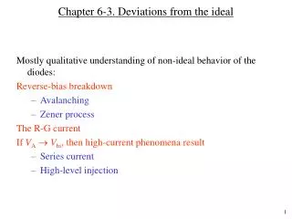
Chapter 6-3. Deviations from the ideal • Mostly qualitative understanding of non-ideal behavior of the diodes: • Reverse-bias breakdown • Avalanching • Zener process • The R-G current • If VAVbi, then high-current phenomena result • Series current • High-level injection
Detailed I-V plots of commercial Si diode at 300 K Forward bias Series resistance effect High level injection Ideal behavior G-R part Reverse bias G-R part Breakdown
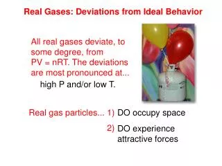
Reverse-bias breakdown A large reverse current flows when the voltage exceeds certain value. Not destructive unless power dissipation causes excessive heating. For a p+n or pn+ diode: VBR NB–1 where VBR is the breakdown voltage and NB is the (bulk) doping on the lightly doped side. Two processes: Avalanching:Dominant process in lightly doped diodes Zener process:More important in heavily doped diodes
E-field PN VA<< 0 Avalanching Carrier multiplication due to impact ionization occurs at high reverse voltage, when the electric field reaches a critical value, ECR. These additional carriers are swept across the depletion layer due the high electric field. The increase in current associated with the carrier multiplication is modeled by introducing a multiplication factor, M (= I / I0) and the multiplication factor can be empirically fit to an equation where m is between 3 and 6.
Carrier activity within a reversed-biased diode Carrier multiplication due to impact ionization
p n E x Emax = q NA xp/ = qND xn/ Avalanching Eq. 5.30a Breakdown occurs when E(0) = ECR;and when (Vbi – VA ) (Vbi – VBR) VBR For asymmetrically doped junctions: (where NB is the (bulk) doping on lightly doped side)
Zener process Tunneling in a reverse biased diode - occurs in heavily doped diodes
The R-G current: reverse-bias case In an ideal diode, the reverse current is I0 = qA [Dp pn/Lp+ Dn np/Ln] and this current is a constant. The ideal diode equation was derived assuming no generation of carriers in the depletion layer. In an actual device, the thermal generation of carriers in the depletion layer should be taken into consideration. The current due to thermal generation (IR-G) increases with the volume of the depletion layer (or W). Volume (or W) increases with the applied reverse bias. So, IR-G increases as reverse voltage is increased. Detailed analysis shows that IR-G for reverse bias can be written as: where 0 = f(p + n) (p + n)/2
The R-G current: forward-bias case Under forward bias, some of the injected carriers may recombine while crossing the depletion layer. This was neglected in the analysis of “ideal” diode. Detailed analysis shows that: ... in the forward bias case. Total forward current: I = Idiff + IR-G where Idiff is the current (called diffusion current) described by the “ideal” diode equation. Idiff increases more more rapidly with bias compared to IR-G. So, Idiff dominates at higher forward voltage.
Relative values of IR-G and Idiff In Si, qAni W/2 >> I0 and IR-G current dominates at reverse bias and at small forward bias. Since IR-G W, the reverse current never saturates, but continually increases with reverse bias. Since Idiff ni2 and IR-G ni, the relative values of Idiff and IR-G varies from semiconductor to semiconductor. In Si and GaAs at 300 K, qAni W/(2) >> I0 whereas in Ge, I0 >> qAni W/(2). So, Ge more closely follows ideal diode equation, I = I0 [exp (qVA/kT) – 1] at 300K. Since Idiff ni2 and IR-G ni, Idiff increases at a faster rate with increasing temperature. So, even Si follows the ideal diode equation, I = I0 [exp (qVA /kT) – 1] at higher temperature.
VAVbi high-current phenomena As VA approaches Vbi, a large current flows. Two phenomena become important: series resistance effect and high-level injection. Series resistance effect: Some voltage drops in the “quasi-neutral” and ohmic-contact region reducing the actual voltage drop across the junction. Here, Vj is the actual voltage across the junction, and VA is the applied voltage. Some of the applied voltage is wasted, so that larger applied voltage is necessary to achieve the same level of current compared to the ideal.
High level injection When the forward voltage is within a few tenths of a volt below Vbi , high current flows, and the low-level injection assumption begins to fail. High level injection phenomena should be considered in deriving I-V characteristics. More detailed analysis shows that the current increases roughly as exp [qVA /(2kT)] when VA Vbi
Review Plot the I-V characteristics for an ideal diode in the same graph above