Beam Transport at ISOLDE: Emittance Measurements and Aberrations
170 likes | 206 Views
This technical report by Mats Lindroos presents findings on beam transport at ISOLDE, emphasizing emittance measurements and classical aberrations. It delves into phenomena affecting beam line performance and provides insights into optimizing emittance control. The report also discusses the importance of emittance characterization for target-ion source units in enhancing beam transport efficiency.

Beam Transport at ISOLDE: Emittance Measurements and Aberrations
E N D
Presentation Transcript
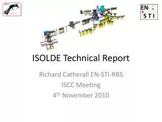
Technical report Mats Lindroos on behalf of The ISOLDE team Mats Lindroos
Outline • Buildings: • Extension building 170 • Class A lab, building 179 • Solid state physics laboratory • Beam transport at ISOLDE • HRS front-end • REX integration • Future EURISOL study Mats Lindroos
Building 170 Mats Lindroos
Planning Mats Lindroos
Planning B.170 • Tendering in progress • Work starts shutdown 2004 • Building completed January 2005 • Dust creating work during shutdown periods • Financed by CERN research sector and the ISOLDE collaboration Mats Lindroos
Solid state Physics lab Mats Lindroos
Class A laboratory Mats Lindroos
Planning Mats Lindroos
Planning • Tendering in progress • Work starts November 2003 • Building completed autumn 2004 • Financed by CERN accelerator sector • Access guaranteed to all of ISOLDE during all the work but expect great constrains on parking space and access to bring in large items Mats Lindroos
Emittance measurements at ISOLDE * Follow up off-line measurements on different source types and operation conditions * Establish emittance at the experimental stations * Measuring points: after HRS magnets, GLM, LA2, RC8 * Both separators provided beam * Surface and hot plasma ion sources * Emittance meters: NTG Gelnhausen slit-grid Munich’s electrostatic beam-deflecting Mats Lindroos
GLM Vertical cut translated in space RC8 RC8 GLM Beam cuts => * smaller geo * lower transmission ‘Classical aberrations’ => * geo remains constant* RMS and encircling emittance grows * transmission is unaffected Phase-space artefacts In spite of the aberrations: all encircling emittances <30 ·mm·mrad Mats Lindroos • The phase-space artefacts noticed during these measurements and presented in the plots above can be divided into two categorises: • Beam cuts - either a cut through the bulk of the beam or shaving of the halos. => Smaller geometrical emittance and lower transmission. • ‘Classical aberrations’ – quadrupole (s-shaped) or sextupole (banana shaped). => The geometrical emittance remains constant, but the RMS and encircling emittance grows. The transmission is unaffected. • Some very large emittance values were recorded, as was expected, but all encircling emittances stayed below 30 ·mm·mrad. As the obtainable focal spot size is strongly dependent on the quadrupole aberrations, and easily can be increased by a factor 2-3 compared with non-aberrated beam, such aberrations should be battled, that means avoiding filling the aperture of the quadrupole lenses. There are no direct means of controlling this, expect for monitoring the emittance or having a reliable model of the beam line implemented in a beam tracing programme to compare with. The aberration is not caused by lens imperfections, but is due to a beam energy variation with radius (correct this Tim??). • If a fraction of beam particle loss is acceptable at the experiment, the encircling emittance can in many cases be decreased notably. Fig. ?8? exemplified this, where the aberrated beam requires a encircling emittance of ~35 ·mm·mrad for a 100% capture of the beam, while a 5% loss (in each plane) reduces the encircling emittance to ~8 ·mm·mrad. • Three phenomena determine the emittance at the end of the beam line: • The inherent ion source emittance and the effects from extraction. A thorough investigation of this is found in ref. [EMIS14 Wenander]. • The beam line scraping that reduces the geometrical emittance and the transmission. In vertical plane by the magnet yoke opening(s) and by obstructing cables; in horizontal plane at kickers and benders (half-gap 15 mm), magnet entrance and by obstructing cables. • The ‘classical aberrations’ (octupol and sextupole) that blow up the RMS emittance and the required encircling emittance. • What can be gained by emittance characterisation of each target-ion source unit? Of course, systematic measurements will give information about emittance variations within the different target-ion source types, which could explain observed variation in beam size and transport efficiency in the separator close to the target. However, from these investigations it becomes clear that a characterisation off-line measurement of each ion source emittance will say nothing about the beam phase-space at the experimental set-up at the end of the beam line. That is instead mainly determined by actual beam line settings, but also the puller position.
Encircling emittance has to be increased, both in x and x’, when the beam becomes aberrated. geo remains constant. (LA2) • Goal • * Avoid filling lens aperture etc • Rely on calc. transport values • Beam delivered up to “last quadrupole” by EIC • Example: Calculated settings • permitted 90-95% efficieny • of transported beam to MISTRAL! Aim Avoid filling the aperture of lenses etc Rely on calculated transport values Exemplify with TnT’s latest progress Aim at using calculated values, reduce time for stable beam setup Not easy to know if and where the beam fills the lenses and if the beam is aberrated Emittance aberrations affect the user 1. Transmission losses 2. Beam focusing 2-3 times larger focal point hitting target frames 3. Poor injection into traps and EBIS Read more about ISOLDE: * beam lines, Wenander et al., future AB note * ion beam transport, T. Giles et al., RNB6 * ion source emittances, Wenander et al., EMIS14 Mats Lindroos • The phase-space artefacts noticed during these measurements and presented in the plots above can be divided into two categorises: • Beam cuts - either a cut through the bulk of the beam or shaving of the halos. => Smaller geometrical emittance and lower transmission. • ‘Classical aberrations’ – quadrupole (s-shaped) or sextupole (banana shaped). => The geometrical emittance remains constant, but the RMS and encircling emittance grows. The transmission is unaffected. • Some very large emittance values were recorded, as was expected, but all encircling emittances stayed below 30 ·mm·mrad. As the obtainable focal spot size is strongly dependent on the quadrupole aberrations, and easily can be increased by a factor 2-3 compared with non-aberrated beam, such aberrations should be battled, that means avoiding filling the aperture of the quadrupole lenses. There are no direct means of controlling this, expect for monitoring the emittance or having a reliable model of the beam line implemented in a beam tracing programme to compare with. The aberration is not caused by lens imperfections, but is due to a beam energy variation with radius (correct this Tim??). • If a fraction of beam particle loss is acceptable at the experiment, the encircling emittance can in many cases be decreased notably. Fig. ?8? exemplified this, where the aberrated beam requires a encircling emittance of ~35 ·mm·mrad for a 100% capture of the beam, while a 5% loss (in each plane) reduces the encircling emittance to ~8 ·mm·mrad. • Three phenomena determine the emittance at the end of the beam line: • The inherent ion source emittance and the effects from extraction. A thorough investigation of this is found in ref. [EMIS14 Wenander]. • The beam line scraping that reduces the geometrical emittance and the transmission. In vertical plane by the magnet yoke opening(s) and by obstructing cables; in horizontal plane at kickers and benders (half-gap 15 mm), magnet entrance and by obstructing cables. • The ‘classical aberrations’ (octupol and sextupole) that blow up the RMS emittance and the required encircling emittance. • What can be gained by emittance characterisation of each target-ion source unit? Of course, systematic measurements will give information about emittance variations within the different target-ion source types, which could explain observed variation in beam size and transport efficiency in the separator close to the target. However, from these investigations it becomes clear that a characterisation off-line measurement of each ion source emittance will say nothing about the beam phase-space at the experimental set-up at the end of the beam line. That is instead mainly determined by actual beam line settings, but also the puller position.
HRS front-end • Front-end renovated • Front part with insulator replaced • Front-end installed in target area • Tests in progress • Promising but we will wait for full test program to be completed before declaring it operational! • Plan to start HRS as scheduled • New front-end type under test at off-line separator Mats Lindroos
REX integration • REX posts: • Two engineer/physicist posts: selection board in progress (1/10 and 7/10) • Two technician posts: selection boards under preparation • Integration process • “Project form” with technical coordinator as “project leader” • Starting end of October Mats Lindroos
Future EURISOL study • Bid from ISOLDE AB and EP to participate in the proposed EURISOL design study (EU 6th FP) • Contribution towards target & ion source, post acceleration, charge breeding, magnetic separators, beam cooling and more • Proposal to include b-beam study in EURISOL (ESGARD, EMCOG) Mats Lindroos
Shutdown 2003-2004 • Two on-line periods: • First on-line period up to Christmas • Second on-line period one month before start-up • Maintenance work and technical improvements • Establish new alignment procedures for “short term” experiments (Erwin Siesling, new EIC) • New control system into full operation • ISOLDE starts with only the LINUX/JAVA system 2004 • Scanners and wire-grids on windows XP consoles • New standard CERN log-book, WWW based • New WWW data screen for ISOLDE separator status • Re-organization of ISOLDE control room Mats Lindroos
Next meeting • ISOLDE shutdown work • Summary of target and ion source developments 2003 • Progress on REX integration Mats Lindroos