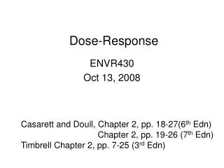
Total Dose
Total Dose. Recombination, Transport, and Trapping of Carries. Current Leakage. Threshold Voltage Shift. From Harris. JPL Total Dose Facility. GSFC Total Dose Facility. TID Dynamic Bias Board w/ Shield. Example TID Static Bias Board Supports In Situ Testing. MIL-Std-883 Method 1019.


Total Dose
E N D
Presentation Transcript
Threshold Voltage Shift From Harris
MIL-Std-883 Method 1019.5 Annealing allowed for parametric failures; not for functional failures. 1019.5 also allows for low dose rate testing.
Lab Instrument 1 Lab Instrument 2 Lab Instrument 3 Lab Instrument 4 Second Generation System - Overview WWW TID Chamber Building TID Chamber DUT “K-labs” GPIB GSFC network “rk” Server “Stupid” PC Test Control PC
“Stupid” - User Interface and Capabilities • Windows 95-based user-friendly Interface • Runs Strip-chart of all Voltages and Currents • Executes remote commands • Monitors chamber conditions • “Stupid” can be configured to control various lab instruments over HPIB • Power Supply • Signal Generator • Multimeter • Digital Oscilloscope
Test Control PC • Can be located anywhere on GSFC computer network • Issues commands for “Stupid” at selected time intervals (or at operator’s discretion) by uploading a command file to “Stupid” PC. • Commands may include • “dump” strip-chart data • send a number of pulses to DUT • measure DUT output voltage • capture and digitize a waveform, etc. • Downloads requested data from “Stupid” • Creates charts and text data files for real-time test monitoring and web posting and post-test analyses.
In Situ Functional Testing • Traditional approach for antifuse-based FPGAs relies exclusively on bias current monitoring • Earlier families of Actel FPGAs (Act1, Act2, Act3) usually show ICC increasing exponentially to relatively high levels (>100 mA) before any irregularities (i.e. high current spikes) are observed; such “spikes” are usually a reliable indication of a functional failure • Initial testing of devices from SX family showed presence of “suspicious” small jumps in ICC current at relatively low current levels ( 10 to 50 mA)
In Situ Functional Testing Example 1 • Actel antifuse-based FPGA device (RT54SX16) • Traditional test configuration (ICC strip-chart) is expanded to include in situ short functional test • Signal Generator is utilized to send stimulus signal(s) to the DUT • Output Voltage(s) are measured by Multimeter • The sequence is executed automatically at programmed time intervals and/or manually as desired by experimenters; functional test results are posted on the web site for convenient monitoring along with ICC strip-chart data • The test, and other subsequent tests of SX family devices, showed that the first small jump in the ICC level usually occurs immediately the functional failure of a DUT
Actel SX Family Device in situ Functional Failure Functional failure occurred at ~15mA; followed by immediate short current spike
In Situ Functional Testing Example 2 • Two Actel SX family devices (same lot, dose rate) irradiated simultaneously. • S/N LAN3403 configured traditionally (static, basic functional test once per hour) - “Static” configuration • S/N LAN3404 is clocked continuously at 1kHz -“Dynamic” configuration • Dynamic device fails at ~8% lower total accumulated dose level than static device “Dynamic” device failure “Static” device failure
Parametric In Situ Testing Example 1 • Flash-based FPGA device (Actel A500K050) • Initial testing involved standard elements • ICC monitoring • In situ basic functional test • Post-irradiation parametric testing showed significant increase in Propagation Delay (tPD) • Consequently, in situ measurement of tPD was added to the test configuration • Signal Generator supplies input pulse for DUT • Waveforms are captured by Digitizing Oscilloscope and tPD is measured
In Situ measurement of Propagation Delay Real-time Digitized Input and Output Waveforms Before irradiation : tPD = 135ns After accumulating 90 krad : tPD = 260ns
Parametric In Situ Testing Example 2 • Low Voltage Dropout Regulator (LM2931CT) • DUT was irradiated at nominal supply voltage (5 V) • Output Voltage strip-charted • In situ parametric testing: • Input Voltage sweep (from 6 V to 3 V) performed • Output Voltage measured and recorded for each sweep
LVDO Regulator Transfer Characteristics Obtained at Various Points during the Test
Isolation Device Input Charge Pump Input Buffer Charge Pump andIsolation FETs from Wang, et. al.
ICC Transient - “New” Part A1280A, 1 V/DIV, 100 mA/DIV
ICC Transient - 6 krad (Si) A1280A, 1 V/DIV, 100 mA/DIV
ICC Transient - Post Anneal A1280A, 1 V/DIV, 100 mA/DIV
XQVR300 Transient Current Voltage and current measurement for SN #42 before irradiation. The measurement is taken with oscilloscope during power-up with the 2 ms-ramp. The current peak observed during the ramp-up of the voltage is according to specification.
XQVR300 Transient Current Voltage and current measurement for SN #42 after the 1st irradiation step (25 krad). The measurement is taken with oscilloscope during power-up with the 2 ms-ramp. The current peak has decreased from the pre-irradiation measurement.
XQVR300 Transient Current Voltage and current measurement for SN #42 after the 2nd irradiation (45 krad). The measurements are taken with oscilloscope during power-with the 2 ms-ramp
XQVR300 Transient Current (4) Voltage and current measurement for SN #42 after the 2nd irradiation (45 krad). The measurements are taken with oscilloscope during power-with the 4 ms-ramp. The over current protection circuit turns off the power (A). By increasing the rise time the device used less current in the power-up phase and the power-up succeeded. [Note, the 4 ms ramp uses a capacitor to slow the power supply's transition time.]
XQVR300 Transient Current (5) Voltage and current measurement for SN #42 after the 3rd irradiation step (75 krad). The measurement is taken with oscilloscope during power-up with the 4 ms-ramp. Both with the 2 ms- and 4 ms ramp the power-up failed. The over current protection circuit for SN #42 is slightly slower than for SN #41. When reaching the maximum current (2.5 A) it takes some microseconds before the power is turned off. [Note, the 4 ms ramp uses a capacitor to slow the power supply's transition time.]
XQVR300 Transient Current (6) Voltage and current measurement for SN #42 after the last irradiation step (95 krad). The measurement is taken with oscilloscope during power-up with the 2 ms-ramp. Both with the 2 ms- and 4 ms ramp the power-up failed. The over current protection circuit for SN #42 is slightly slower than for SN #41. When reaching the maximum current (2.5 A) it takes some microseconds before the power is turned off.
VCC Ionizing Radiation Control Gate ONO Tunnel Oxide Floating Gate Source Drain Data Path Total Dose Effects on FLASH Switch • Ionizing radiation discharge the floating gate • Increase ON-state NMOS transistor resistance, increase RC delay in the data path • Increase OFF-state NMOS sub-threshold leakage, increase ICC
T1 T2 T3 T = T1 · T2 · T3 Total Dose Effects on FLASH Switch Tunnel Oxide Radiation-Induced Traps • Radiation-Induced Leakage Current (RILC) in tunnel oxide • Similar to Stress-Induced Leakage Current (SILC) cause discharge of the floating gate • Charge retention cause long term reliability issue Floating Gate Silicon
Low Dose Rate Test andAnneal - A1280A from chiba