Download
1 / 27
270 likes | 399 Views
EGR 110 – Inventor Lecture #3. Drawing Files So far we have printed directly from sketches or from the model view of a part ( ipt ). A better approach is to create a drawing file ( idw ) in Inventor. From the drawing file we can: Insert a part (a specified view)

E N D
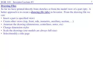
EGR 110 – Inventor Lecture #3 • Drawing Files • So far we have printed directly from sketches or from the model view of a part (ipt). A better approach is to create a drawing file (idw)in Inventor. From the drawing file we can: • Insert a part (a specified view) • Create other views (top, front, side, isometric, auxiliary, section, …) • Annotate the drawing (dimensions, centerlines, notes, etc) • Change dimension styles • Scale the drawings (our models are always full size) • Select/modify a title page
EGR 110 – Inventor Lecture #3 Inventor Part (ipt) Inventor Drawing (idw)
EGR 110 – Inventor Lecture #3 • Example: • Create a part (such as Prob 4 on sheet A-2 (page D-23) in Engineering Graphics Text and Workbook, Series 1.2, by Craig & Craig). • Add convenient dimensions (which will later be imported into a drawing file). • Save the part and remember the name (such as Part2.ipt) Note: It is a good idea to decide how you want an object to be oriented and then choose an appropriate 2D sketch plane to begin. In this case beginning with a front view will work well. y x Front z Front View 2D Sketch Plane
EGR 110 – Inventor Lecture #3 Creating a Drawing File After creating the part, create a New Filein Inventor and select a Standard.idw drawing file and then select Create.
EGR 110 – Inventor Lecture #3 Selecting the sheet size Inventor will open a C-size sheet (17 x 22) by default. We will only use A-size sheets in this course (8.5 x 11), so we need to change the sheet size. C-size sheet A-size, Portrait, 1 view Right-click on Sheet1 and select Edit Sheet Change Size from C to A size, Portrait, 1 view
EGR 110 – Inventor Lecture #3 • Adding a Base View • Add a “base view” to the drawing file from which other views will be obtained. In the example below, the front view is selected as the base view for Part2.ipt. • Select Base view • Select the File or Inventor part (Part2.ipt) • Select the Orientation (front, top, etc) • Move the mouse over the drawing page and select where to place the view Select location of front view
EGR 110 – Inventor Lecture #3 Adding Other Views Immediately after adding the base view, you can move the mouse to other locations to add a right view, top views, isometric, etc. Right click and select Create when done. Note: You can also use the Projected Viewtool to add views at any time. 1) Add right view 2) Add top view 3) Add isometric view then select Create 4) Final result
EGR 110 – Inventor Lecture #3 Changing the Scale Note on the last slide that the views are somewhat small. The default scale is 1:1 (full scale). To change the scale: • Move the mouse over the base view until a dotted box appears around the view. Right-click in the dotted box and select Edit View. • Change the Scale to 2:1 to make the view twice as large (or use another scale factor). • Note that this affects all orthographic views. The isometric view as its own scale factor so it must be changed separately.
EGR 110 – Inventor Lecture #3 Changing the Scale • In the example shown: • The scale was changed to 2=1 on the front view which affected the top and right views as well. • The scale was also changed to 2=1 on the isometric view (it has a separate scale factor) Scale 1=1 (Full Scale) Scale 2=1
EGR 110 – Inventor Lecture #3 Moving Views Recall that with orthographic projection (multiview drawings) views must always be properly aligned. So moving one view in Inventor may cause other views to move. If the front view is the base view, then: • Moving the base view will move the top and right views also to keep them aligned. • The top view can only be moved up and down so that it stays aligned with the front view. • The right view can only be moved left and right so that it stays aligned with the front view. Moving the front view – top and right move also Moving the right view – it will only move left or right
EGR 110 – Inventor Lecture #3 Retrieving Dimensions If dimensions were added to sketches used to create a part, the dimensions can be retrieved for use in the drawing file. Before adding dimensions, move the views to space them out nicely on the drawing sheet. To retrieve dimensions for the front view: • Move the mouse over the front view until a box appears and right-click inside the box. Select Retrieve Dimensions… • Pick Select Dimensionsand the available • dimensions will appear
EGR 110 – Inventor Lecture #3 Retrieving Dimensions (continued) • Select the desired dimensions that you wish to retrieve. The selected dimensions will change color. • Select Apply when finished and close the Retrieve Dimensions window.
EGR 110 – Inventor Lecture #3 Retrieving Dimensions (continued) • Similarly, retrieve desired dimensions in other views. • Dimensions are not typically shown in the isometric view.
EGR 110 – Inventor Lecture #3 • Dimension Style • Good style in dimensioning will be covered in detail a little later in the course, but for now a few useful rules are presented below: • Keep dimensions aligned as much as possible • Neatly space the dimensions • Avoid inside dimensions • Avoid driven (redundant) dimensions • Center the dimension text within the extension lines • Specify diameter (using ) for holes and radius (using R) for arcs • Label views (neatly centered under each view) • Always include the scale for the drawing • Use centerlines where appropriate • Generally include overall dimensions (total width, height, and depth) • Use a consistent precision (number of digits after the decimal point) • Dimensions should be shown in the view where the feature is clearest • Locate holes by their centers, not by their edges
EGR 110 – Inventor Lecture #3 • Dimension Style (continued) • The recently retrieved dimensions violate a number of rules for dimensions. Some problems to correct are noted below. Poor location Number of digits: This value should be 0.375 Missing centerlines Label each view Poor location. Omit one and add overall depth. Wrong view
EGR 110 – Inventor Lecture #3 • Dimension Style (continued) Problem: Poor location. Omit one and add overall depth. Solution: Move one dimension, delete another, and add a new dimension (use Annotate menu). Problem: Wrong view. Solution: Delete 0.15 dimension in front view and add a new dimension in the right view. Original Original Improved Improved
EGR 110 – Inventor Lecture #3 Centerline Bisector tool • Dimension Style (continued) • Problem: Missing centerlines. • Solution: Use tools in Annotation menu: • Center Mark tool to add center lines in top view. • Centerline Bisector tool to add centerline in front view (pick lines on either side and the centerline will be inserted between them) Center Mark tool Improved Original Another problem has now occurred: The centerline in the front view has no dash. Solution: See next slide
EGR 110 – Inventor Lecture #3 • Dimension Style (continued) • Problem: No dashes in centerline in front view. • Solution: Change the Global Line Scale for line types as follows: • Select Styles Editor under the Manage menu. • Select Standard – Default Standard ANSI • Change Global Line Scale from 1 to 0.5 to make all dashes half size. Note that this affects all line types, including hidden lines. Improved Original
EGR 110 – Inventor Lecture #3 • Dimension Style (continued) • Problem: Incorrect number of digits • Solution: It is common to use the same number of digits after a decimal point for all dimensions, indicating a common precision. To change the number of digits from 2 to 3 for all dimensions: • Select Styles Editor under the Manage menu. • Select Dimension – Default (ANSI) • Change Precision from 2.12 to 3.123 to use three digits after the decimal point for all dimensions. Original Improved
EGR 110 – Inventor Lecture #3 • Dimension Style (continued) Problem #1: Wrong view. Solution: Delete dimension (.375) in front view and add a new dimension in the top view. Problem #2: Poor location. Solution: Move R.175 as it is over a visible line. Also avoid inside dimensions, so move it outside. Original Improved
EGR 110 – Inventor Lecture #3 Label Views and Add Title Block Information Use Annotate – Text to label views and to add title block information. Adjust view spacing if necessary. Improved Original
EGR 110 – Inventor Lecture #3 Volume and Density For some parts and assemblies, it is important that we use the correct materials or assign the correct density to each part so that the center of gravity (or center of mass) will be in the correct location (for balance perhaps). Example: The part shown below was created to model an AA battery. The battery’s mass was determined to be 23 g using a digital scale. Adjust the density of the part so that its mass is correct.
EGR 110 – Inventor Lecture #3 Determine the part’s original mass and volume • Right-click on the part name (AA_Battery) in the Model browser and select iProperties. • Select the Physical tab Original mass: 0.008 kg = 8 g Original volume: 8183.669 mm3
EGR 110 – Inventor Lecture #3 Determine the required density • We just determined the original mass and volume using the values from iProperties: • Convert the required density from kg/mm3 to lb/in3. This can be done using dimensional analysis, using a calculator, or using an online program. The density with these units will be entered in Inventor Inventor will display the result with these units. http://www.digitaldutch.com/unitconverter/
EGR 110 – Inventor Lecture #3 Change the Material type • Select Material under the Tools menu • Note that the current material is Generic • Right-click on any unused material and pick Rename to assign it a new name. • The name AA_Battery was used in this case.
EGR 110 – Inventor Lecture #3 Change the Material type (continued) • AA_Battery now appears in the Inventor Material Library • Double-click on AA_Battery to add it to the list of Document Materials • The Material Editor window should now be open with the properties for AA_Battery. • Note that the density is 0.306 pound per cubic inch (lb/in^3). • Change the density to 0.101535 lb/in^3, press the Enter key, and select Apply.
EGR 110 – Inventor Lecture #3 Change the Material type (continued) • Right-click on AA_Battery under Document Materials and select Assign to Selection (this assigns the new material to the part). • As done previously, right-click on the part name (AA_Battery) in the Model browser and select iProperties. • Select the Physical tab. • Check to see if the mass has been changed • to the desired value. Correct mass: 0.023 kg = 23 g