Download
1 / 24
260 likes | 547 Views
Learn about the physics and procedures involved in the start-up phase of a tokamak discharge, from creating fully ionized plasma to operating the tokamak. Key steps include pre-ionization, capacitor banks activation, and monitoring toroidal magnetic and electric fields. Understand the importance of plasma density, pressure, and magnetic flux in achieving successful plasma start-up. This talk will delve into the complexities and scientific principles essential for a successful tokamak operation.

E N D
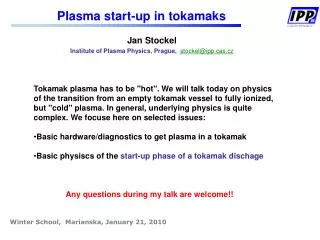
Jan Stockel Institute of Plasma Physics, Prague, stockel@ipp.cas.cz Plasma start-up in tokamaks • Tokamak plasma has to be "hot". We will talk today on physics • of the transition from an empty tokamak vessel to fully ionized, but "cold" plasma. In general, underlying physics is quite complex. We focuse here on selected issues: • Basic hardware/diagnostics to get plasma in a tokamak • Basic physiscs of the start-up phase of a tokamak dischage • Any questions during my talk are welcome!! Winter School, Marianska, January 21, 2010
Tokamak basics • Tokamak is composed of • three basic components • Large transformer with primary winding • Plasma ring as secondary winding • Coils for confinement of plasma ring by magnetic field (toroidal solenoid) • Electric currentI generated in the plasma ring by the transformer • delivers the ohmic power Pohmic = I2Rplasmato plasma (heating) • generates the poloidal magnetic field in the plasma ring Bpoloidal ~I/2pa However, before ohmic heating, we have to fill the tokamak vessel by fully ionized plasma. This period is called as start-up or breakdown phase of the tokamak discharge. It is a complex process, which begins from well evacuated toroidal vessel. This talk just tackle about basic physics.
Sequence of events before a tokamak discharge 1 • Tokamak is pumped down to to the pressure < 10-4 - 10-3 Pa. • Baking of the vessel to 150-2500 and glow discharge cleaning is required! • Then, the tokamak vessel is filled by a working gas – but what pressure? • At normal conditions (105 Pa, T = 273.15 K) we have n0 = 2,7×1025 m−3 H2 molecules (Loschmit number), i.e. 5.4 ×1025 m−3 atoms is available • We require the plasma density ~ 1018 - 1019 m-3 at the breakdown phase. Density of neutral atomic hydrogen should be comparable. • Therefore, the initial pressure of H2 should be in the range ~ 0.02 - 0. 2 Pa
Sequence of events before a tokamak discharge 2 Grid Rectifier Capacitor bank Toroidal FieldCoils Capacitor bank Grid Rectifier Primary winding of transformer • Some free electrons have to be generated inside the vessel by some extermal source (pre-ionization) • electron gun • VUV lamp • cosmic radiation background • eventually RF assisted pre-ionization • At least, two power supplies (capacitor banks) to be activated (charged) to drive: • *current in the toroidal magnetic field coils • * current in primary winding of the transformer
Start-up ofa tokamak discharge • A trigger pulse is applied to start the data acquisition system • Experimental data are collected • 2. A trigger pulse is applied to discharge the capacitor bank UBt to toroidal field coils • Toroidal magnetic field is generated inside the vessel • Wait until a reasonable level of the toroidal magnetic field is reached. (GOLEM – a typical time delay is 1 - 4 ms) • 4. A trigger pulse is applied to discharge the capacitor bank Uoh to primary winding of the transformer • Time-dependent current in the primary winding generates the toroidal electric field inside the vessel
Toroidal electric field – how to measure? Toroidal electric fieldEtoris required plasma breakdown in tokamaks and for inductive current drive. Etor is generated by transformer (iron- or air-core) by primary current I(t), which has to vary in time. dy/dt – magnetic flux The toroidal electric fieldis measured by a single loop located along the plasma column: dIprim/dt 0 E tor = Uloop/2pR Loop voltage Uloop = - dy/dt
Why the E tor (loop voltage) must be as low as possible during the breakdown? Magnetic flux through the primary windings of a tokamak transformer F(t) = Vloop(t) dt < Fmax Maximum flux Fmax [Weber = Voltseconds] is limited either by quality of the iron core transformer or by mechanical properties of the central solenoid (air-core transformer) CASTOR/GOLEMFmax = 0.12 Vs (iron core) COMPASSFmax = 0.64 Vs – (air-core) (0,4 Vs for breakdown and current ramp-up + 0,24 Vs for flat top phase) ITER Fmax = 277 Vs – (air-core) Iron-core transformer F ~ B*S [Vs] Fmax Air-core transformer H ~ Iprim
Trigger Uoh Trigger Bt Delay Sequence of events during a discharge Pressure of Hydrogen 50 mPa Toroidal magnetic field Loop voltage Uloop is high enough – Breakdown phase Time
Start-up phase of a discharge on CASTOR Loop voltage [V] Uloop Fully ionized plasma – "hot" (~200 eV) Toroidal current [kA] I_plasma+ I_vessel Fully ionized plasma – "cold" (5-10 eV) Plasma density ne[1018 m-3] 4 0 2 6 Time [ms] I_vessel = I_plasma – Uloop/Rvessel
Avalanche & Coulomb phases of breakdown • Plasma start-up can be divided into two phases with different underlying physics. Therefore, they have to be treated separately. • Avalanche phase – degree of ionization is low. Collisions between electrons and hydrogen molecules dominate. Electrons obey a drift velocity vD II Etor, which is higher than their thermal velocity. Plasma current is still low, and the rotational transform is negligible. • Coulomb phase – collisions between charged particles dominate. Plasma current is sufficiently high and magnetic surfaces and the confinement is expected to increase significantly. • Transition between these two phase occurs when [eV] where g is the degree of ionization. Typically, the transition occurs in tokamaks at 5% ionization at Te ~5 eV
Electron are accelerated in toroidal direction and ionize the working gas Fully ionized plasma fills the vessel (in 0.1-10 ms – depending on the size of tokamak) Density of charged particles increases exponentially in time Free electron(s) appear in the vessel
ITER Lion~ 2000 m COMPASS GOLEM Avalanche phase of breakdown – ionization length First Townsend coefficient a [m-1] Ionization length Lion[m] Pressure p0 [Pa] E=Uloop/1pR [V/m] For hydrogen (H2) A = 3.75, B = 99 Ionization length versus E
Drift velocity & Ionization time during the avalanche Electrons obtain a drift velocityvd between ionization collisions, which depends on the ratio of the toroidal electric field and pressure of molecular hydrogen E/p . Only approximation of vd is available for H2: Approx. for 70<E/p<1500 [V/m, Pa] [m/s, V/m, Pa] Typically E/p = 80-800 Vd~0.55–2*106 m/s Note: For E/p > 500 , the electron distribution function becomes strongly non-Maxwellian and a significant fraction of electron can run-away! Temporal evolution of plasma density is: where the ionization time tiis defined as ti ~ Lion/ vd . Typically, ti~ 20 ms at p0 ~30 mPa Example: Our final goal is to reach degree of ionization 5%, i.e. the plasma density 5x10¹⁷ m-3 with just a single electron inside the tokamak vessel (n0=1 m-3). This occurs during the time interval t = 17 x ln5 x 20 x 10-6~550 ms !!! HOWEVER – this appears in an ideal case, when all electrons remain inside the vessel during the avalanchel!!
Connection length & Loss time during the avalanche REALITY The magnetic field is not strictly toroidal during the start-up. It always has a perpendicular component B, which significantly impacts trajectories of charged particles during the avalanche phase of the discharge. Example B = Bz We can define the connection lengthLcon ~ a Btor/ B and an effective loss lime tloss ~ Lcon / vd Rate of the density increase is consequently reduced: and eventually the breakdown may not occur when Lion ~ Lcon In practice,the condition Lion ~ 10 x Lcon should be fulfilled
Stray magnetic field B from the Toroidal Fieldcoils View from the top , A strong vertical fieldBzis created (oriented downwards) Installation of Return Current Conductor significantly reducesthe Bz field Nevertheless, a small fraction of Bz (<1 mT) could still exists inside the tokamak vessel because of imperfect alignment of TF coils and the return conductor!! Bz = m0I/2pr I = 1 kA, R = 0.4 m Bz(center) ~ 0.15 T !!
Stray magnetic field B from the vessel current Toroidal current through the tokamak vessel (without plasma) generates a vertical magnetic field inside the tokamak vessel Rough estimate (linear approx – lower limit): For 2r = R = 0.8 m and I = 2 kA Bz ~ 0.25 mT For GOLEM a~0.08 m, Btor ~ 0.25 T, B ~ 0.25 mT Lcon ~ 8 m only !!
Stray magnetic field from the air-core transformer COMPASS case The vertical field is significantly reduced, when the primary current flows also through properly distributed poloidal coils. Strong vertical field is generated, when the primary current flows only through the central solenoid
Evolution of plasma current during the avalanche Plasma current grows exponentially with approx. the same rate as the plasma density during the avalanche phase Iplasma = S*e*ne(t)*vD(t) where S is the cross section of the current channel S=pa2 [m-2] e= 1.6*10-19 C vD(t) =const ~ 106 m/s is the average drift velocity At the end of the avalanche phase, the plasma density is g* nmax with the degree of ionization g = 0.05 and nmax = 1019 m-3 So, the plasma current at the end of the avalanche phase should be Iplasma(end of avalanche) ~ 8*104 x S [A]. If the current flows through the whole cross section, then: GOLEM (S~0.02 m-2) I ~ 1.6 kA COMPASS (S~0.12 m-2) I ~ 9.6 kA TORE Supra (S~1.6 m-2) I ~ 130 kA
Coulomb phase of the start-up Particle balance during the Coulomb phase is described by differential equation for electrons and neutrals Si – rate of ionization by electrons tp – particle confinement time L – particle influx (recycling) Solution for tp infinity, L 0 where N is initial number density of H ti is the ionization time in Coulomb phase
Dynamics of atomic/molecular species Dissociation cross section of H2 is greater than the ionization one at low Te Result of modeling including dissociation Te = 6 eV, NH2 ~ 7x 10¹⁸ m-3
Ionization rate for atomic hydrogen The ionization rate is a steep function of guessed electron temperatures (3 – 10 eV] [m3/s] where U = 13.6/Te [eV] Approximation for Te < 10 eV: [m3/s, eV] Ionization time at the Coulomb phase for Te = 5 eV and N = 1019 m-3 is longer than during the avalanche
Power losses due to collisions with atomic hydrogen ionization losses excitation losses Energy loss per a single ionization/excitation of H0 Ionization and excitation rates are comparable Energy losses are maximum when N=1*1019 and Te = 6 eV Ploss~ 200 kW/m3
Power balance at start-up Power losses due to the collisions have to be compensated by ohmic heating CAST0R- Ohmic power during start up: Volume 0.1 m3, Vloop~ 10 V, Ip ~ 2 kA Poh ~ 200 kW/m-3 The electron temperature can be roughly estimated from the power balance CASTOR N= 1019 m-3 and POH~200 kW/m-3Te ~ 7.2 eV This number is an upper limit for Te – some fraction of POH is consumed to heat electrons
Conclusions • I tried to explain some underlying physics of the plasma start-up in • tokamaks. • Two phases were defined • * Avalanche phase • * Coulomb phase • We focus on the avalanche phase • importance of ionization and connection lengths (stray magnetic fields) • Many relevant features were not discussed at all (role of impurities, RF assisted pre-ionization, runaway electrons, plasma current ramp-up, …..) • More information is available in many publications upon request at • stockel@ipp.cas.cz • Thanks for attention those who did not sleep, but also to sleepers, who did not snore!!