Download
1 / 14
140 likes | 184 Views
This project focuses on building a Laser Sensor Brick with Sick LMS-200, developing acquisition software for real profile display, and testing data acquisition and analysis. It covers hardware and software architecture, GUI design, and future work.

E N D
Implementation of the Laser Range Sensor Brick –Sick LMS 200 Santosh Katwal ECE 574 Final Presentation April 29, 2004
Outline • Objective • Hardware Architecture • The Brick Architecture • Overall Design • Brick Layout • Brick Structure • Software Architecture • GUI • Sample Images • Conclusion and Future Work
Objective This project has following objectives: • To build the Laser Sensor Brick comprising Sick LMS-200 designed in the last semester in ECE 573. • To write an acquisition software having an option for the continuous real profile display for the operation of the brick. • To test the Brick for acquiring data and analyzing the result.
Hardware Architecture Brick Architecture
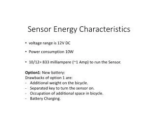
Overall Design of the Brick (Hardware Architecture Contd…) Power -Panasonic-LCRA1212P 12V Battery Acquisition- Sick LMS -200 Vicor Dc-Dc RS-422 Communication- Linksys Wireless-G PCI Card PW-70A Dc-Dc Processing-ASUS P4GE-VM micro ATX board
Brick Structure (Hardware Architecture Contd…) Top View Side View Front View Different Face of the Brick (Loose)
Software Architecture Steps for Operation: Select the Port and Initial Default Speed of 9600 bps. Open the Port and Wait for the Scanner to Respond. Enter the ‘Enter Config Mode’ Button. Enter the ‘Change Baud’ Button to Change the Speed of the Scanner to 500 Kbps. Check the LMS Status to Make Sure that the Maximum Baud Rate is Achieved. Enter ‘Continuous Scan Button’ to Start Scanning, Meanwhile the profile and the image will be seen GUI for the Acquisition (Designed in Visual C++ Builder)
Software Architecture Demo of off-line profiles and Image Display
Software Architecture Contd… Scan time 8.99 Second Speed of Scanning 46 Profiles Per Second Sample Gray Level Image of a Box on the table (703 *888) (Using XYZ-theta Table)
Software Architecture Contd… Color Coded Format
Conclusion and Future Work • The Hardware Architecture of the brick is completed. It is tested with success. Frames have to be built to package the brick into one unit. • The GUI for the Acquisition is built. It gives the real time display of the continuous scan and the respective profile image. It also gives the total scan time and the profiles per second. The software can be modified in the future to add options for preprocessing of the images.