Instructions for Use, Gridlock Ankle Plating System - DJO Global
20 likes | 38 Views
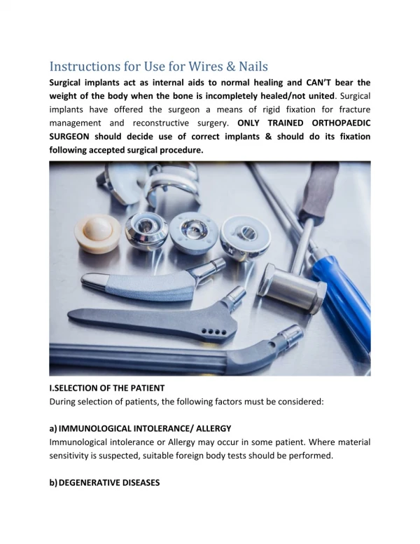
Comprising a variety of contoured titanium plates with different shapes and sizes, the Gridlock Ankle Plating System is designed for internal fixation. The Gridlock Ankle Plating System utilizes solid core threaded standard and locking screws, cannulated screws, and syndesmotic screws in various diameters and lengths. The plates, screws, and guide wires are intended for single use only. To know more visit https://www.djoglobal.com/sites/default/files/IFU/Gridlock-Ankle-Plating-System-IFU-900-01-011-Rev-M-July-2020.pdf or call us at 800.321.9549.tttt

Instructions for Use, Gridlock Ankle Plating System - DJO Global
E N D
Presentation Transcript
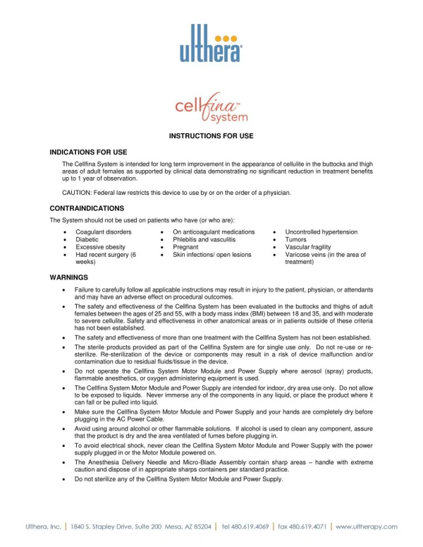
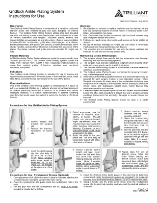
Gridlock Ankle Plating System Instructions for Use 900-01-011 Rev M | July 2020 Description The Gridlock Ankle Plating System is comprised of a variety of contoured titanium plates with different shapes and sizes designed for internal fixation. The Gridlock Ankle Plating System utilizes solid core threaded standard and locking screws, cannulated screws, and syndesmotic screws in various diameters and lengths. Available plates, screws and instrumentation are packaged as a single system. System instrumentation includes drill bits, countersinks, guide wires, depth gauges, bone clamps, bending instruments, drill guides, drill sleeves, a screw removal tool, driver shafts, handles, and ancillary instruments to facilitate the placement of the plates. The plates, screws, and guide wires are intended for single use only. Warnings 1. Re-operation to remove or replace implants may be required at any time due to medical reasons or device failure. If corrective action is not taken, complications may occur. 2. Use of an undersized implant in areas of high functional stresses may lead to implant fracture and failure. 3. Instruments, guide wires, olive wires, and screws are to be treated as sharps. 4. Re-use of devices indicated as single use can result in decreased mechanical and clinical performance of devices. 5. The washers are not intended for use with the plates; washers are intended for use with non-locking screws only. Implant Materials All Gridlock Ankle Plating System plates are made from commercially pure Titanium (ASTM F-67). All Gridlock Ankle Plating System screws are made from Titanium Alloy (ASTM F-136). Associated instrumentation is made from medical grades of titanium, stainless steel, anodized aluminum, and plastic. Maintaining Device Effectiveness 1. The surgeon should have specific training, experience, and thorough familiarity with the use of plating systems. 2. The surgeon must exercise reasonable judgment when deciding which plate and screw type to use for specific indications. 3. The Gridlock Ankle Plating System is not intended to endure excessive abnormal functional stresses. 4. The Gridlock Ankle Plating System is intended for temporary fixation only until osteogenesis occurs. 5. All Gridlock Ankle Plating System implants and instrumentation may be required for each surgery. Failure to use dedicated, unique Trilliant Surgical instruments for every step of the implantation technique may compromise the integrity of the implanted device, leading to premature device failure and subsequent patient injury. Failed devices may require re-operation and removal. 6. Carefully inspect the implants prior to use and inspect the instruments before and after each procedure to assure they are in proper operating condition. Instruments that are faulty, damaged or suspect should not be used. 7. The Gridlock Ankle Plating System should be used in a sterile environment. Indications The Gridlock Ankle Plating System is intended for use in trauma and reconstructive procedures of the small bones in the hand/foot, ankle, distal tibia, fibula, and other bones appropriate for the size of the device. Contraindications Use of the Gridlock Ankle Plating System is contraindicated in cases of active or suspected infection or in patients who are immunocompromised; in patients previously sensitized to titanium; or in patients with certain metabolic diseases. It is further contraindicated in patients exhibiting disorders that would cause the patient to ignore the limitations of internal fixation. Instructions for Use, Gridlock Ankle Plating System 5. Select desired screw diameter and the corre- sponding pilot drill. 6. Select the corresponding drill guide and place it into the first plate hole nearest the fracture line or osteotomy site. 7. Drill the pilot hole with the corresponding drill diame- ter at the desired angle of approach through the drill guide. Note: It is recom- mended to irrigate during pilot drilling. 3. Select appropriate plate for fixation of fracture, oste- otomy, or fusion. Though plates are pre-contoured, slight adjustments may be required and made using the plate bending instruments. Warning: Excessive or mul- tiple plate bends could cause weakness in the plate. 4. Apply the plate to the pre- pared site. The plate may be temporarily fixated with either olive wires or K-wires. 1. Identify, expose, and prepare the surgical site. 2. Reduce the fracture, osteotomy, or fusion site. 9. Select desired screw length and type. Insert screw into the pilot hole and drive into position rotating clockwise with the driver. Note: If variable angle drill guide is used, locking screw placement angle is possible up to 5° off axis. 8. Insert the depth gauge into the pilot hole to d e t e r m i n e s c r e w length. Note: Gridlock ankle screw length is measured tip to tip. There are no threads on the distal end of the screw. 10. Repeat steps 5-9 until all desired screw holes are filled. When placing ad- ditional screws, make sure placement does not interfere with other screws. Note: The syndesmotic holes are not intended for locking screws. Instructions for Use, Syndesmotic Screws (Optional) 1. Once placement of all desired screws in plate is complete, stabilize the syndesmotic joint using the syndesmotic bone clamp. 2. Place the syndesmotic drill guide inside the syndesmotic hole in the plate. 3. Drill the pilot hole with the syndesmotic drill bit. Note: It is recom- mended to irrigate during drilling. 4. Insert the Gridlock Ankle depth gauge in the pilot hole to determine screw length. Note: Syndesmotic screws are intended to be measured from the tip to the thread breakout feature. Do NOT measure the head. 5. Using a handle and the ankle screw driver, drive the syndesmotic screw into the pilot hole rotating clockwise until the desired position is achieved. Page 1 of 2 900-01-011 Rev M
Instructions for Use, Tiger Cannulated Screws (Optional) eIFU: www.trilliantsurgical.com/regulatory Packaging and Sterility NON-STERILE PRODUCT The Gridlock Ankle Plating System (instruments and implants) can be packaged non-sterile and therefore must be sterilized prior to surgical use. Use of the sterilizer shall comply with the manufacturer’s user instructions. The user facility must clean and disinfect instruments prior to sterilization per standard hospital procedures. Non-sterile devices are sterilizable by steam sterilization (autoclaving). The following parameters should be followed: 1. Reduce fracture, osteotomy, or fusion site. 2. Insert appropriate K-wire to the correct length under image intensification. Avoid bending the K-wire by inserting in 15mm - 20mm increments. 3. Slide the countersink over the guide wire until the countersink tip contacts bone. Rotate the countersink clockwise and counterclockwise to create the necessary recess in bone. 4. Slide the appropriate depth gauge over the K-wire advancing until the depth gauge contacts bone. Measure for the desired screw length by examining the end of the K-wire in relation to the marks on the depth gauge. 5. It is recommended to pre-drill to reduce the axial force necessary for inserting the screw in cases of dense bone. 6. Remove the desired Tiger Cannulated Screw from the screw block. Slide the screw over the K-wire. 7. Using a handle and the appropriate driver, drive the Tiger Cannulated Screw into bone rotating clockwise until the desired fixation is achieved. 8. Remove and discard the guide wire. Sterilization Method Condition Temperature Time Dry Time * The system shall be packaged for sterilization by double wrapping in standard central supply wrap (i.e. Bio-Shield® Sterilization Wrap). ** Trilliant Surgical has validated the recommended sterilization cycle and dry time for trays. The dry time varies due to load configuration, wrapping method, and material. Pre-Vacuum Steam Wrapped* 270°F (132°C) 10 minutes Recommended 50 minutes** CAUTION Federal Law (USA) restricts this device to sale by or on the order of a physician. Do not attempt a surgical procedure with faulty, damaged or suspect Trilliant Surgical instruments or implants. Inspect all components preoperatively to assure utility. Instructions for Use, Solid Core Interfrag Screws (Optional) An interfragmentary screw may be used in conjunction with a plate. If using a solid core interfrag screw, follow the lag technique for solid core fully threaded screws. 1. Reduce fracture, osteotomy, or fusion site. 2. Place the desired diameter drill guide on determined site for screw placement. Drill glide hole in proximal cortex/section of bone. 3. Place the corresponding drill guide inside glide hole and drill pilot hole through distal cortex using the appropriate pilot drill. 4. Countersink the proximal cortex. 5. Using the lag depth gauge, determine the length of the screw required. 6. Select appropriate screw length and insert rotating clockwise with the driver until the desired position is achieved. MRI Safety Information The Gridlock Ankle Plating System has not been evaluated for safety and compatibility in the MR environment. It has not been tested for heating, migration, or image artifact in the MR environment. The safety of the Gridlock Ankle Plating System in the MR environment is unknown. Scanning a patient who has this device may result in patient injury. Symbols Glossary Plate Removal (If Necessary) 1. Locate plate and screws with intra-operative imaging. 2. Palpate plate and remove surrounding soft tissue to gain maximum exposure. 3. Engage screw heads with appropriate driver and rotate counter- clockwise until screws are removed. 4. Use forceps to remove plate. 5. All devices removed should be treated as medical waste and disposed of accordingly. Designation Number, ISO 15223-1:2016 Symbol Description Catalog Number 5.1.5 Batch Code 5.1.6 Do not use if package is damaged 5.2.8 Cleaning Non-sterile products must be carefully cleaned prior to sterilization. Trained personnel must perform cleaning and mechanical inspection prior to sterilization. Compliance is required with the equipment manufacturer’s user instructions (manual and/or machine cleaning, ultrasound treatment, etc.) and recommendations for chemical detergents. For validated cleaning instructions, please reference document 900-06-010, Gridlock Ankle Plating System Cleaning and Sterilization Protocol. Do not reuse 5.4.2 Non-Sterile 5.2.7 Device only to be sold on or by the order of a physician N/A* Manufacturer 5.1.1 Caution 5.4.4 Consult instructions for use 5.4.3 *Symbol allowed under 21 CFR 801. The above symbols are outlined in ISO 15223-1:2016 Medical devices -- Symbols to be used with medical device labels, labeling and information to be supplied -- Part 1: General requirements. Note: QTY is an abbreviation of “QUANTITY”. Please contact company for product inquiries and surgical techniques, or to report any adverse experience. This document is controlled by Trilliant Surgical. When downloaded, printed, and/or copied, this document becomes UNCONTROLLED and users should always check Trilliant Surgical’s website, www.trilliantsurgical.com, to ensure they have the latest version. Trilliant Surgical 727 North Shepherd Drive | Suite 100 | Houston, TX 77007 1-800-495-2919 | trilliantsurgical.com Page 2 of 2 900-01-011 Rev M