Information Technology
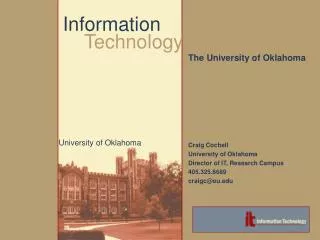
Information Technology . Computer Architecture Dr. John P. Abraham. Computer Architecture. The computer architecture is a branch of study that deals with designing of processors their instruction sets organizing various components to facilitate most efficient communication between them

Information Technology
E N D
Presentation Transcript
Information Technology Computer Architecture Dr. John P. Abraham Dr. John P. Abraham
Computer Architecture • The computer architecture is a branch of study that deals with • designing of processors • their instruction sets • organizing various components to facilitate most efficient communication between them • without significantly increasing cost. Dr. John P. Abraham
Digital Computers • Analog • Digital • Distinct binary signals • Instruction set • Predetermined by circuitry Dr. John P. Abraham
CISC/RISC • CISC • More instructions in the instruction set • Easier for programmers • More complex and slower machines • RISC • Simpler instructions • Fewer instructions Dr. John P. Abraham
A computer • Input/output • Processor • ALU • Control Unit • Registers • Connecting busses Dr. John P. Abraham
Basic Operation of a CPU • Obtain instructions kept in the memory, one at a time • Decode • Execute • Write the result back Dr. John P. Abraham
Binary number system • Calculate value of 11110101 in decimal • Number from right to left Digit value Value • 1 11 x 1 = 1 • 0 20 x 2 = 0 • 1 41 x 4 = 4 • 0 80 x 8 = 0 • 1 161 x 16 = 16 • 1 321 x 32 = 32 • 1 641 x 64 = 64 • 1 1281 x 128 = 128 • Total245 Dr. John P. Abraham
Signed binary • signed-magnitude • The most significant bit (MSB) is set aside to indicate the sign, zero for positive and 1 for negative. • One’s-complement • The MSB of a negative number will begin with a one and a positive number with a zero. 0011 will represent +3 and 1100 (complement of the positive 3) will represent -3. • Two’s-complement. • a negative number is represented by complementing the bits of the positive number and adding a 1. a –3 is represented as 1101 (complement of 0011 is 1100, and add a 1). Dr. John P. Abraham
Two’s complement • a binary number’s MSB is a zero then it is a positive and no further action is necessary. • If the MSB is 1, it is a negative number. • Suppose the number is 10000001, we know it is a negative number. Complement the bits and add a 1, we get 01111110 +1 = 01111111 which is 127. • The sign is already determined to be negative it is –127. Dr. John P. Abraham
ASCII Character Set • a specific binary sequence must be established for representing the alphabets, numeric symbols and other special symbols that are in use in English as well as other languages of the world. • An agreement was reached in 1968 to represent all English alphabets • The standard ASCII character set consists of 128 decimal numbers ranging from zero through 127 • The Extended ASCII Character Set also consists of 128 decimal numbers and ranges from 128 through 255 representing additional special, mathematical, graphic, and some foreign characters. Dr. John P. Abraham
ASCII Character Set • The first 32 (0 to 31) ASCII codes are for special purposes such as line feed, carriage return, form feed, bell, etc. • The ASCII can only represent languages that use Roman Alphabets such as English. • To represent an ASCII character we need 7 bits and an extended ASCII character requires 8 bits; therefore, we set aside a byte for it and a byte happens to be the smallest addressable memory unit. Dr. John P. Abraham
Unicode • Unicode provides a unique number for every character regardless of the platform, the program, or the language. • Unicode uses two bytes to represent one character. This means we can have 65,536 possible symbols in a given alphabet. • encoding scheme that IBM mainframes used is the Extended Binary Coded Decimal Interchange Code (EBCDIC). Dr. John P. Abraham
Numbering schemes • Binary • Octal • Since the basic addressable memory unit is a byte an octal (base eight) makes sense and some early computers used the octal system. Octal numbering system uses 8 symbols, 0 to 7. The next number after 7 is 10. • Hexadecimal Dr. John P. Abraham
Hexadecimal • Hexadecimal (base 16) numbers give more compactly written numbers and programmers use it very often. • It uses 15 symbols 0-9 and A-F. The A stands for decimal 10, B for 11, C for 12, D for 13, E for 14 and F for 15. • These 15 symbols can be represented using four bits or a nibble. For example , 1111 will represent F (decimal 15). • Two hexadecimal digits can be represented in one byte; FF representing 255. • After the F, the next number is 10 (decimal 16). Dr. John P. Abraham
Boolean Operations • The mathematics used in digital systems is the special case of Boolean Algebra. • the variables only assumes only two values (0 or 1). • The basic operations of Boolean Algebra are: NOT, AND, OR, XOR, NAND and NOR. Dr. John P. Abraham
Not gate • The NOT operation gives the inverse (complement) of a Boolean variable. For example NOT(True) is false. Dr. John P. Abraham
AND gate • The AND operation is a logical multiplication. • An example: IF US CITIZEN AND AGE GREATER THAN OREQUAL TO 18 THEN ELIGIBLE TO VOTE. • There are two inputs, citizenship and age, and one output, voting eligibility, in this example. • In a situation where a person is a US citizen and 20 years of age, the inputs will be TRUE and TRUE. The output also will be TRUE. If one or both of the inputs are FALSE then the output will be FALSE. Dr. John P. Abraham
AND gate Dr. John P. Abraham
OR gate • The OR operation is a local addition. • An example: If grade == 90 or grade >90 then Grade = ‘A’. • In an OR operation only one condition has to be true for the output to be true. Dr. John P. Abraham
OR gate Dr. John P. Abraham
XOR gate Dr. John P. Abraham
NOR Gate Dr. John P. Abraham
Half Adder #include <iostream.h> void main() { short x,y, sum, carry; bool a,b,c,d; cout <<"Enter two bits to add seperated by a space ";cin >> x>>y; a=x==1; b=y==1; //actually c++ assigns 0 for false and 1 for true, we could have read these directly; c=(a||b) && !(a&&b); d=(a&&b); 9 sum=c?1:0; //if c is true then sum gets 1 else sum gets 0 carry=d?1:0; cout <<x <<"+"<<y <<"="<<carry<<sum<<endl; if (a = true) cout <<"it is true"; if (a) cout << "it is ture"; } Dr. John P. Abraham
Computer Programming Languages • Computers perform operations such as moving data and data manipulation by activating switches and gates. • Instructions to do that also must be given in the form of 1s and 0s or on and off. • When we program computers using just ones and zeros we are using the “machine language”. Dr. John P. Abraham
Structure of 8088 Microprocessor • execution unit (EU) • the bus interface unit (BIU) Dr. John P. Abraham
Execution Unit (EU) • the control logic for decoding and executing instructions • ALU for performing arithmetic and logic operations • A set of general purpose registers Dr. John P. Abraham
Bus interface unit (BIU) • A bus is a set of wires that connects the various components of a computer together and transfers signals and data between them. • The number of lines a bus has depends on the architecture of the microprocessor and is directly proportional to the CPU speed. • ControlDataAddress Dr. John P. Abraham
3 Functions of the BUS • memory address transfers, data transfers and control signal transfers. • One set of physical wires may handle all three operations one at a time, or there may be different sets of wires for each, the address bus, data bus and the control bus. • If we say that the hypothetical processor is 16 bit, then 16 bits of data should be transferred at the same time. Dr. John P. Abraham
Major microprocessor components • PC- Program Counter • MBR- Memory Buffer Register • MAR- Memory Address Register • ALU- Arithmetic Logic Unit • IR- Instruction Register • General Purpose Registers. Dr. John P. Abraham
Microprocessor operation • When a program begins execution, the program counter (PC, a register inside the CPU) has the address of the next instruction to fetch. • this address is placed there initially by the operating system and updated automatically by the CPU. • There are three additional registers, the instruction register (IR), memory address register (MAR) and the memory buffer register (MBR) that work together to fetch the instruction. Dr. John P. Abraham
Microprocessor Operation (2) • The address from the PC is moved to the MAR. • The reason for this is that the address bus is connected to the MAR and all addresses issued must go through this register. • Then the address contained in the MAR is placed on the address bus and the READ line is asserted on the control bus. Dr. John P. Abraham
Microprocessor Operation(3) • The memory whose address is found on the address bus places its contents on the data bus. • The only register that is connected to the address bus is the MBR, and all data should go in an out through this register. • Thus the data on the address bus is copied into the MBR. The instruction is now copied on to the IR to free up the MBR to handle another transfer. Dr. John P. Abraham
Microprocessor Operation(4) • The contents of the PC will be now incremented by one instruction. • The instruction is then decoded and executed. • In practice, more than one instruction is read during an instruction cycle. Additional instructions are kept in temporary storage registers such as the Instruction Buffer Register (IBR). Dr. John P. Abraham
The Program Counter • The size of the PC depends on the number of address lines of the CPU. • Let us assume that the CPU has 16 address lines. Then the PC should be able to address 65,536 locations. • Initially the CPU starts its operation based on the contents of the PC. Assume that initially the PC contains the value 0000h where “h” stands for hexadecimal notation. Dr. John P. Abraham
The Fetch Cycle • MAR holds the address of the memory location from which the instruction is to be fetched. • At the start up, the CPU performs an instruction fetch. • Instruction fetch involves reading the instruction stored in the memory. • The location from which the instruction is read is derived from the PC. Dr. John P. Abraham
The Decode Cycle • An instruction will have an opcode and none, one or more operands (data to operate on) • The opcode is defined as the type of operation the CPU has to perform. • The number of bits assigned to the opcode will determine the maximum number of instructions that processor is allowed to have. Dr. John P. Abraham
Opcode • suppose that the length of an instruction (opcode and operand) is 16 bits, 4 bits are allocated for the instructions and the remaining 12 bits are allocated for an operand. • Four bits can give us a maximum of sixteen instructions. Each of these 16 bit patterns, ranging from decimal 0 to 15, or binary 0 to 1111, or hexadecimal 0 to F will stand for a particular instruction. Dr. John P. Abraham
Instruction set of an imaginary computer Dr. John P. Abraham
Operations of a Microprocessor • This hypothetical computer has only one user addressable register, which is the accumulator (AC). • When a load (LD) is executed, the contents of the register as indicated by the operand is brought into the AC • The reverse happens in a store (ST). Dr. John P. Abraham
Operations of a Microprocessor(2) • When an add (A) is executed, the value contained in the memory location as indicated by the operand is added to the contents of the AC, and the result is placed back in the AC. • The add immediate (AI) differs from the add (A) in that the operand is what is added, not the content of the memory pointed by the operand. Dr. John P. Abraham
Program Example • B = B + A • C = B + 2 • The variable A is kept in memory location 200h • Variable B in 201h • Variable C in 202h. • The values in each are 5, 3 and 0 respectively. Dr. John P. Abraham
Program Example (2) • There are three registers that need watching, the Accumulator (AC), Program Counter (PC), and the Instruction Register (IR). • The PC contains 100h, which means that the next instruction should be fetched from memory location 100 hexadecimal. Dr. John P. Abraham
Program Example (3) – The code Dr. John P. Abraham