Download
1 / 29
290 likes | 441 Views
Chipcon 802.15.4 Transceiver. EECS150 Spring 2006 Lab Lecture #8 David Lin. Project Overview. N64 Controller User input to your game. Video Game output to the user. Chipcon Transceiver: the “FUN” Two-Week One! =) Bidirectional communication between games. Game Engine

E N D
Chipcon 802.15.4 Transceiver EECS150 Spring 2006 Lab Lecture #8 David Lin EECS150 Lab Lecture #8
Project Overview • N64 Controller • User input to your game. • Video • Game output to the user. • Chipcon Transceiver: the “FUN” Two-Week One! =) • Bidirectional communication between games. • Game Engine • Drives game play. “Glue logic.” Handles communication handshaking. EECS150 Lab Lecture #8
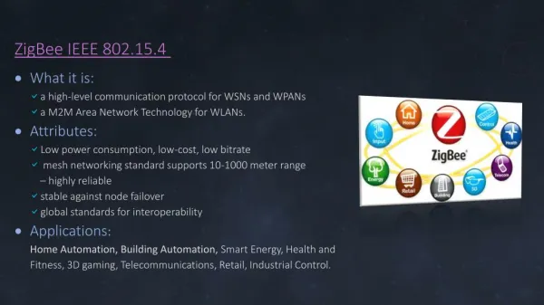
Transceiver Overview (1) • 3rd party chip mounted on expansion board. • Uses a PCB antenna. Take a look! • IEEE 802.15.4 standard support. Zigbee ready. • Transmits on unlicensed 2.4 GHz spectrum. 16 communication channels. • Overlaps with Wi-Fi. • 250 kbps maximum data rate. • We will only be using a very small percentage of this. • Configure, send, receive, and issue commands to chip over SPI to CC2420 registers. EECS150 Lab Lecture #8
Transceiver Overview (2) • 33 configuration registers. • We change 3 of them. • 15 command strobe registers. • We issue 6 of them. • These change the state of the CC2420 internal FSM. • 128-byte RX FIFO & 128-byte TX FIFO • Accessed via 2 additional registers. • Also accessible as RAM (i.e. by addressing). Only for debugging! Probably not necessary. EECS150 Lab Lecture #8
CC2420 Inputs & Outputs • Single bit status signals. • High level transceiver operation information. • Initialization signals. • Drive signals once and forget about it. • SPI interface. • Interface to rest of chip via CC2420 registers. • Send, receive, configuration, detailed status. FPGA VREG_EN RF_RESET_ EECS150 Lab Lecture #8
Single Bit Status Indicators • FIFO – Goes high when there’s received data in RX FIFO. • FIFOP – Goes high when # bytes received exceeds set threshold. • CCA – Indicates that the transmission medium (air) is clear. Only valid after 8 symbol periods in RX mode. • SFD – Goes high after SFD is transmitted & low after packet completely sent. EECS150 Lab Lecture #8
SPI Interface • Serial interface with 4 wires: • SClk – Clock signal you generate. • CS_ – Active-low chip select. • SI – Output to the CC2420. • SO – Input from the CC2420. • Described earlier in class lecture. • Interface to the chip! Initialization, configuration, TX, RX, detailed status. • Luckily for you, it’s provided as a black box. EECS150 Lab Lecture #8
CC2420-specific SPI (1):First Byte • First byte always has above format. • Bit 7 – Set to 0 for register access. • Bit 6 – Read/write control. • Bits 5:0 – Address of register. P. 60 of datasheet. • Followed by data specific to register being accessed. EECS150 Lab Lecture #8
CC2420-specific SPI (2):Writing to Configuration Reg. • First byte followed by 2 bytes of configuration data. • Data on SO invalid here. • Transceiver replies when first byte is sent out with status byte. • True for all SPI accesses. • Not necessary to inspect, but can be helpful for debugging! EECS150 Lab Lecture #8
CC2420-specific SPI (3):Issuing Command Strobes • One byte only. Nothing follows. • Address sent indicates the command strobe being issued. • Note that 0x00 is NO OP. This is useful for explicitly retrieving status byte. EECS150 Lab Lecture #8
CC2420-specific SPI (4):Saving to TX FIFO • After first byte, send n bytes of data to transmit over wireless. • SPI session only ends when CS_ is pulled high. • CC2420 replies with a new status byte with each byte that’s saved to FIFO. EECS150 Lab Lecture #8
CC2420-specific SPI (5):Receive from RX FIFO • After first byte, send a n bytes of “don’t care” in order to receive data. • During first byte, CC2420 replies with status. Subsequent bytes are data saved in FIFO. • Must be careful not to request data from empty FIFO! • SPI session only ends when CS_ is pulled high. • Reading from a configuration register is the same. EECS150 Lab Lecture #8
Configuration Registers EECS150 Lab Lecture #8
Command Strobe Registers EECS150 Lab Lecture #8
TX/RX FIFO Registers EECS150 Lab Lecture #8
Initialization EECS150 Lab Lecture #8
Transmit EECS150 Lab Lecture #8
Receive (1) EECS150 Lab Lecture #8
Receive (2) • Packets are only received after CC2420 has spent 12 symbol periods in receive mode. • There must be wait time between transmissions. • Allows the transceiver to look for and receive data. EECS150 Lab Lecture #8
Announcements • Next week’s lab lecture is Thursday 8-9P. Come with questions! • Groups have been assigned channels and addresses. Check online grade book. EECS150 Lab Lecture #8
Design Structure (1) EECS150 Lab Lecture #8
Design Structure (2) • Transceiver – Highest level block. 32-bit input/output, channel changing, addressing. • SPI Abstraction – Takes care of details of CC2420 SPI interface. Arbitrates between TX/RX. • SPI (provided) – Handles details of interface timing. • SPIFifo (provided) – Storage place for filtered, received data. EECS150 Lab Lecture #8
Packet Format • On transmit, only fill TX FIFO starting with length byte. • Preamble & SFD automatically appended. • Transmit all zeros for CRC. CC2420 will replace. EECS150 Lab Lecture #8
Channel & Addresses • There are 16 channels. • Your group has been assigned a channel. • You must be able to change channels without reset! • Address are 8-bits wide 256 addresses. Zero is unused. 0xFF is reserved for broadcast. • Your group has been assigned 2 addresses. EECS150 Lab Lecture #8
Interference & Debugging • Roughly 2-3 groups per channel. Each group in a particular lab has distinct channel. • Can also pick up data on neighboring channel. • Very first goal is robust channel changing during initialization. • Can pick up 802.11 packets sometimes. • Your module must recover gracefully. • Your project interferes with Wi-Fi & vice versa. EECS150 Lab Lecture #8
Handshaking:InRequest/Invalid • SPI uses a variation of this. • You may want to use this internally. EECS150 Lab Lecture #8
Handshaking:Ready/Start • Transceiver uses this interface for input & output. EECS150 Lab Lecture #8
Debugging Tools • Chipscope! • We will be releasing some debugging utilities. • Packet sniffer. • Packet counter. EECS150 Lab Lecture #8
Get Started! • Don’t count on spring break. • This is meant to replace a ~50 hour (avg.) SDRAM checkpoint. • There are many subtleties that you must address (e.g. when are RX flushes used?). • I will monitor newsgroup over spring break, but less frequently. • Next week’s lab lecture is CP3 Q&A. Come with questions. • Read the datasheet! EECS150 Lab Lecture #8