Download
1 / 53
540 likes | 595 Views
Learn about LR-WPAN applications, topologies, architecture, physical & MAC layers, and superframe structure in this concise guide on the IEEE 802.15.4 protocol for low-data-rate wireless connectivity.

E N D
802.15.4 Samer Shammaa Telecommunications Eng. Dept. Dr. Pramode Verma
Outline • Introduction • WSN Applications • Topologies • Architecture • Physical Layer • MAC Layer • Superframe structure
Introduction • Until recently, the main concern in wireless communication was on high throughput • Some applications need a different set of requirements • Example: LR-WPAN applications -Low cost communication network -Limited power -Low throughput • Require: reasonable battery life, extremely low cost, short range operation, reliable data transfer
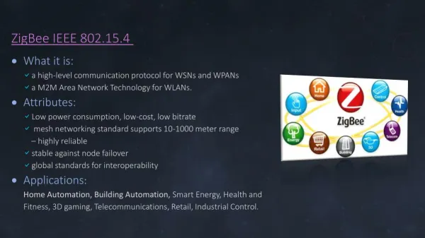
Solution? • Existing standards not suitable for these applications b/c of complexity, power consumption, and high cost. • Need a simple, flexible protocol • IEEE 802.15.4 defines protocol via RF for PAN. • Provide a standard with ultra-low complexity, cost, and power for low-data-rate wireless connectivity among inexpensive fixed, portable, and moving devices.
Device Types • Full function device (FFD) • Any topology • PAN coordinator capable • Talks to any other device • Implements complete protocol set • Reduced function device (RFD) • Limited to star topology or end-device in a peer-to-peer network. • Cannot become a PAN coordinator • Very simple implementation • Reduced protocol set
Modes of Operation • Network Device: An RFD or FFD implementation containing an IEEE 802.15.4 medium access control and physical interface to the wireless medium. • Coordinator: An FFD with network device functionality that provides coordination and other services to the network. • PAN Coordinator: A coordinator that is the principal controller of the PAN. A network has exactly one PAN coordinator.
Combined Topology • Ex: hotel where cluster nodes exist between the rooms of a hotel and each room has a star network for control.
Star Network Formation • After an FFD is activated, it can establish its own network and become the PAN coordinator • Choose a PAN Identifier different from surrounding networks (within RF sphere of influence) • The PAN coordinator allows other devices, potentially both FFDs and RFDs, to join its network.
Peer-to-peer Network Formation • Each device is capable of communicating with any other device within its radio sphere of influence • One Device is nominated as the PAN coordinator • Form first cluster by choosing an unused PAN identifier and broadcasting beacon frames to neighboring devices. • A candidate device receiving a beacon frame may request to join the network at the PAN coordinator. • If the PAN coordinator permits the device to join, it adds the new device as a child device in its neighbor list.
Continued… • Newly joined device adds the PAN coordinator as its parent in its neighbor list and begins transmitting periodic beacons • Other candidate devices may then join the network at that device. • Once predetermined application or network requirements are met, the first PAN coordinator may instruct a device to become the PAN coordinator of a new cluster adjacent to the first one. • Other devices gradually connect and form a multi-cluster network structure
Physical Layer • Provides two services: -PHY data service -PLME-SAP providing data and management services to upper layers.
PHY Data Service • Enables the transmission and reception of PHY protocol data units (PPDUs) across the physical radio channel • Activation and deactivation of the radio transceiver • Energy detection within the current channel • Link quality indication for received packets • Clear channel assessment for CSMA-CA • Channel frequency selection • Channel switching
Operating Band • 2.4GHz band operates worldwide- offers 250kb/s • 868 MHz band operates in Europe- offers 20 kb/s • 915 MHz band operates in United States- offers 40kb/s
PHY Frame Structure • The 32-bit preamble is used for synchronization • “11100101” indicates start of packet • 7 out of the 8 PHY header bits are used to indicate the length of the PSDU • The PSDU has a variable length between 0 and 127 bytes
MAC Layer • The MAC sublayer provides two services: -MAC data service: enables the transmission and reception of MAC protocol data units (MPDUs) across the PHY data service -MLME-SAP: provides data and management services to upper layers
MAC Sublayer Features • Beacon management • Channel access • Guaranteed Time Slot (GTS) management • Frame validation • Acknowledged frame delivery • Association • Disassociation • Provides means for implementing application-appropriate security mechanisms
MAC Frame Types • IEEE 802.15.4 defines 4 types of MAC frames: • Beacon Frame • Data Frame • Acknowledgment Frame • MAC Command Frame
Data Frame Format Acknowledgment Frame Format
Command Frame Format • Association request • Association response • Disassociation notification • Data request • PAN ID conflict notification • Orphan Notification • Beacon request • Coordinator realignment • GTS request
Superframe Structure • The active portion is divided into 16 equally sized slots • During the inactive portion, the coordinator may enter a low-power mode • The beacons are used to synchronize the attached devices, to identify the PAN, and to describe the structure of the superframes
Guaranteed Time Slots (GTSs) • For low-latency applications or applications requiring specific data bandwidth • PAN coordinator may dedicate portions of the active superframe to that application • PAN coordinator may allocate up to seven of these GTSs, and a GTS may occupy more than one slot period
Data Transfer • Three types of data transfer: -Data transfer to a coordinator in which a device transmits the data -Data transfer from a coordinator in which the device receives the data -Data transfer between two peer devices *In star topology only first two are used *The mechanisms for each transfer type depend on whether the network supports the transmission of beacons
Data Transfer to a Coordinator • Beacon-enabled PAN • Slotted CSMA-CA • Nonbeacon PAN • Unslotted CSMA-CA
Data Transfer from a Coordinator • PAN indicates message is pending in the beacon frame • Device request data at application-defined rate
Peer-to-peer Data Transfers • Devices wishing to communicate will need to either receive constantly or synchronize with each other • In the first case, the device can simply transmit its data using unslotted CSMA-CA • In the latter case, other measures need to be taken in order to achieve synchronization
Improving Probability of Successful Delivery • The IEEE 802.15.4 LR-WPAN employs various mechanisms to improve the probability of successful data transmission: • CSMA-CA mechanism • Frame acknowledgment • Data verification
Unslotted CSMA-CA Mechanism • Used by nonbeacon-enabled PANs • Each time a device wishes to transmit data frames or MAC commands, it waits for a random period • If the channel is found to be idle, following the random backoff, the device transmits its data • If the channel is found to be busy following the random backoff, the device waits for another random period before trying to access the channel again • Acknowledgment frames are sent without using a CSMA-CA mechanism
Slotted CSMA-CA Mechanism • Used by beacon-enabled PANs • Backoff slots are aligned with the start of the beacon transmission • Device locates the boundary of the next backoff slot and then waits for a random number of backoff slots • If the channel is busy, following this random backoff, the device waits for another random number of backoff • If the channel is idle, the device begins transmitting on the next available backoff slot boundary
Frame Acknowledgment • A successful reception and validation of a data or MAC command frame can be optionally confirmed with an acknowledgment • If the originator does not receive an acknowledgment after some period, it assumes that the transmission was unsuccessful and retries the frame transmission • When the acknowledgment is not required, the originator assumes the transmission was successful
Data Verification-FCS Mechanism • In order to detect bit errors, an FCS mechanism employing a 16-bit International Telecommunication Union—Telecommunication Standardization Sector (ITU-T) cyclic redundancy check (CRC) is used to detect errors in every frame
Approaches for Low Power • The protocol has been developed to favor battery-powered devices • Battery-powered devices will require duty-cycling to reduce power consumption • Thus will spend most of their operational life in a sleep state • Each device periodically listens to the RF channel in order to determine whether a message is pending • Higher powered devices have the option of listening to the RF channel continuously
Service Primitives • The services of a layer are the capabilities it offers to the user in the next higher layer or sublayer by building its functions on the services of the next lower layer
Continued… • Each event consists of passing a service primitive from one layer to the other through a layer SAP associated with an N-user • Service primitives convey the required information by providing a particular service • A service is specified by describing the service primitives and parameters that characterize it
Primitive Types • — Request: The request primitive is passed from the N-user to the N-layer to request that a service is initiated. • — Indication: The indication primitive is passed from the N-layer to the N-user to indicate an internal N-layer event that is significant to the N-user. This event may be logically related to a remote service request, or it may be caused by an N-layer internal event. • — Response: The response primitive is passed from the N-user to the N-layer to complete a procedure previously invoked by an indication primitive. • — Confirm: The confirm primitive is passed from the N-layer to the N-user to convey the results of one or more associated previous service requests.