TRANSFORMER
TRANSFORMER. . C. i p. N p. v p. P.


TRANSFORMER
E N D
Presentation Transcript
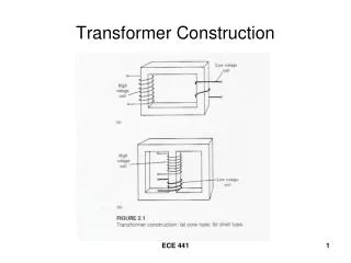
C ip Np vp P A transformer consists of a core made of laminated iron separated by insulators and a coil of Np turns wound around the core. This coil is supplied with an a.c voltage supply vp which then produces a current ip. Due to this current , a flux F is produced which is given by an equation • = Npip/S…….(1) where S is the reluctance
Since current varied with time , F also varied with time. A back electromagnetic force (e.m.f) will be produced which is given by the equation. ……(2) Substitute = Npip/S into the above equation , then ……(3)
If ip is sinusoidal, the flux produced also sinusoidal, i.e = msin 2ft ……(4) therefore vp = NP2fmcos 2ft= NP2fmsin (2ft + /2) ……(5) The peak value = Vpm = NP2fm and vp is leading the flux by p/2. ……(6) The rms value ……(7)
secondary primary C is ip Np Ns vs Load vp P S When another coil is wound on the other side of the core with no of turns Ns , then the fux will induce the e.m.f vS as given by ……(8)
From (2) and (8) we get …….(9) …….(10) Or in rms value With load , is will flow in the load, mmf at load will equal to the mmf at input, then (in rms value) NpIp = NsIs …….(11) rearrange …….(12)
Primary Secondary NP : NS VP VS Symbol for ideal transformer For ideal transformer, the energy transferred will be the same as input. Thus power at primary is same power at secondary. Pp = Ps or IpVp = IsVs
Example 1 A 250 kVA,11000V/400V, 50Hz single –phase transformer has 80 turns on the secondary. Calculate (a) The appropriate values of the primary and secondary currents; (b) The approximate number of primary turns; (c) the maximum value of the flux. (a) Full-load primary current Full-load secondary current
(b) Number of primary turns recall (c) Maximum flux recall
IO NP EP VP NS VS Ideal transformer with no load Io is the no load current when the secondary is open circuit. This current consists of Iomthat isrequired to produce the flux in the core (it is in phase) and Io1 is to compensate the hysteresis and eddy current losses.
fo EPVP IO IOI IOm VS Phasor diagram for no load transfomer VP= emf of supply to the primary coil and 90o leads the flux. EP=emf induced in the primary coil and same phase as VP. VS=emf induced in the secondary coil and 90o lags the flux. Iom=magnetizing current to produce flux and it is in phase with flux. Io1=current to compensate the losses due to hysteresis and eddy current. Io=the no load current and given by Power factor
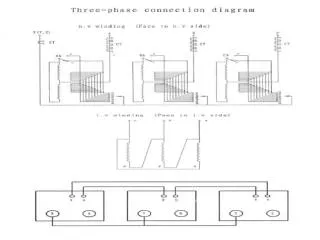
Transformer 1 Highvoltageline Transformer 2 Low voltage generator Low voltage load Application of transformer Transformer converts the energy to high electrical voltage and transmits in the high voltage line. At the load, the high voltage energy is converted to low voltage. In this way, it will compensate the losses during transferring of the voltage energy.
Example 2 A single-phase transformer has 480 turns on the primary and 90 turns on the secondary. The mean length of the flux path in core is 1.8m and the joints are equivalent to the airgap of 0.1mm. The value of the magnetic field strength for 1.1 T in the core is 400A/m, the corresponding core loss is 1.7W/kg at 50Hz and the density of the core is 7800kg/m3. If the maximum value of the flux is to be 1.1T when a p.d of 2200V at 50Hz is applied to the primary, calculate: (a) the cross-sectional area of the core; (b) the secondary voltage on no load; (c) the primary current and power factor on no load
(a) recall recall Practically 10% more allow for insulator (b) recall
(c) magnetomotive force (mmf) for the core is mmf for the airgap is Total mmf is recall Maximum magnetizing current Rms value
Volume of core mass of core Core loss= loss rate x mass Core-loss component of current No load current Power factor
Phasor diagram ‘ I1 I2 E1 V1 V2 L(2) Loaded transformer Loaded transformer L(q2)= load with power factor of cos q2 V1 = emf at supply E1=induced voltage at primary V2=emf at load E2=induced voltage at secondary I1= primary current I2=secondary current
Example 3 A single-phase transformer has 1000 turns on the primary and 200 turns on the secondary. The no load current is 3A at a power factor 0.2 lagging when secondary current is 280A at a power factor of 0.8 lagging. Calculate the primary current and the power factor. Assume the voltage drop in the windings to be negligible. Recall Equation 12 therefore
‘ Solve for horizontal and vertical components Power factor
I1 R1 L1 I1’ L2 R2 RC Lm V2 E1 V2’ Equivalent circuit of transformer Leakage fluxes Path of leakage Flux leakage is due to secondary current that produce flux which encounter the primary flux. Some of the flux will link to its own windings and produce induction. This is represented by inductance L1. Similarly with the flux in secondary and represented by L2.
E1 I1 R1 L1 I1’ L2 R2 RC Lm V2 V1 E2 Equivalent circuit of transformer • There are four main losses • Dissipated power by wire resistance of the windings (I2R) • Power due to hysteresis • Power due to eddy current • Power via flux leakages. R1= wire resistance of primary windings L1=inductance due to leakage flux in primary windings RC=resistance represent power loss due to in hysteresis and eddy current Lm= inductance due to magnetizing current Iom L2=inductance due to leakage flux in secondary windings R2=wire resistance of secondary windings
V1 -I2’ I1 E1 f1 I1Z1 I1R1 I1X1 I0 I2R2 I2X2 f2 I2Z2 I2 V2 E2 Phasor diagram for a transformer on load
Simplified/approximate equivalent circuit We can replace R2 by inserting R2’ in the primary thus the equivalent resistance is Giving us Similarly
Ze I1 I2 To load V1 E2=V2 E1=V2’ Transformer simplified circuit then where and
fo-f2 Complete Phasor diagram of simplified equivalent circuit of transformer Magnified Ze portion
Voltage regulation of a transformer recall Secondary voltage on no-load V2 is a secondary terminal voltage on full load Substitute we have
Or From phasor diagram can be proved that Or
Example 4 • A 100kVA transformer has 400 turns on the primary and 800 turns on the secondary. The primary and secondary resistances are 0.3W and 0.01W respectively, and the corresponding leakage reactances are 1.1W and 0.035W respectively. The supply voltage is 2200V. Calculate: • The equivalent impedance referred to the primary circuit; • The voltage regulation and the secondary terminal voltage for full load having a power factor of (i) 0.8 lagging and (ii) 0.8 leading. • The percentage resistance and leakage reactance drops of the transformer
(a) (b) (i)
Sec. terminal voltage on no-load The decreasing of full-load voltage is Therefore the secondary full-load voltage (b) (ii) power factor 0.8 leading The increasing of full-load voltage is Therefore the secondary full-load voltage
Or Per unit
Alternative Recall Equation 12 Full load secondary current Equivalent resistance referred to secondary Secondary voltage on no-load