Download
1 / 16
170 likes | 353 Views
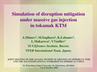
Simulation of disruption mitigation under massive gas injection in tokamak KTM. A.Mineev 1 , M.Sugihara 2 , K.Lobanov 1 , L.Makarova 1 , V.Vasiliev 1 1 D.V.Efremov Institute, Russia; 2 ITER International Team, Japan;.

E N D
Simulation of disruption mitigation under massive gas injection in tokamak KTM A.Mineev1, M.Sugihara2, K.Lobanov1, L.Makarova1, V.Vasiliev1 1D.V.Efremov Institute, Russia; 2ITER International Team, Japan; JOINT MEETING OF THE 3rd IAEA TECHNICAL MEETING ON SPHERICAL TORI AND THE 11th INTERNATIONAL WORKSHOP ON SPHERICAL TORUSSt. Petersburg State University, St. Petersburg, RUSSIA3 to 6 October 2005
Introduction • For plasma current quench stage electromagnetic pressure pv on in-vessel components of a tokamak is scaled as pv IP2/cq, where IP is plasma current before disruption and cq is plasma current decay time. So, search of methods of EM loads mitigation, especially possibilities of current quench time increasing is important. • Value cq usually is defined by the rate of plasma current magnetic energy dissipation due to impurity radiation. It is supposed that large amount of impurities comes into the plasma during thermal quench stage (basic case of disruption) or after massive gas injection from gas jet reservoir (noble gas injection for plasma mitigation). • Model for description of plasma current behaviour IP(t) must include: • plasma resistance model (include elastic and nonelastic collisions with electrons and neutrals); • impurity radiation model (full collisional-radiation model); • generation of runaway current (include Dreicer and avalanche generation). • Report is devoted mainly to the study of plasma current decay problems after impurity gas injection in KTM tokamak with use of DIMRUN model.
1 DIMRUN 0D code description For analysis of the process of plasma current shut down after impurity injection 0D code DIMRUN was developed (Dynamics of IMpurity radiation and RUNaway generation in tokamaks). Three sorts of impurities are taken into account: carbon and noble gases neon and argon. Carbon impurity corresponds to non mitigated case. Mitigation is analysed with Ne and Ar injection. 1.1 Energy balance equations System of equations includes balance of thermal energy and magnetic energy. Here QOH = (IP-IR). Ures is ohmic heating power, Qzis radiation power; Q is energy exchange term between electrons and ions, ni is total concentration of ions, VP is plasma volume; Ures=RPL.(IP- IR) is active plasma loop voltage, RPL = e.2Ro/(ka2) is plasma resistance, E|| = Ures/2Ro is vortex field on the plasma loop, e is plasma resistivity, IR is runaway current, Ee, Ei are energy losses due to disturbance of magnetic field during impurity injection.
1.2 Plasma resistivity model Total plasma resistivity is a sum where of ei correspond to elastic electron-ion collisions, ea – to electron-atom collisions and en – to nonelastic electron collisions (which lead to ionisation, excitation, recombination etc.). Elastic e-i collisions: eiCoulomb 10-4.Cs,C·Zeff. ·ln/Te1.5 [.m, eV] Elastic e-a collisions: where <H0v>, <z0v> for hydrogen and impurities (C, Ne, Ar) are obtained from experimental values. Inelastic e-a, e-i interaction Below inelastic collisions means processes of interactions of electrons with atoms and ions, which results in transition between energy levels (ionisation, recombination, excitation). Inelastic collisions gives following contribution to plasma resistivity where Ij and Rj are rate coefficients for ionisation and recombination; H , jZ correspond to energies of ionisation and L is a function of radiation.
1.3 Impurity radiation model Model of dynamics of ionisation state of impurities is used for simulation of impurity ionisation states evolution nj(t). It includes the following set of equations dn0/dt = -ne·n0·I0 + ne.·n1·R1 + nH0·n1·X1 + Sz dnj/dt = ne·nj-1·Ij-1 - ne·nj(Ij + Rj) + ne·nj+1·Rj+1 + nH0· (nj+1·Xj+1-nj·Xj), j=1...Z-1 dnz/dt = ne·nz-1·Iz-1 - ne·nz·Rz – nH0·nz·Xz where n0, nj is concentration of neutral and jth ionized ion; nH0 is concentration of neutral hydrogen; Ij, Rj and Xj are rate coefficients for ionization, recombination and charge exchange. Radiation power for impurity can be represented as a sum of contribution from all ionisation states where Uk are radiation coefficients.
If during disruption electrical vortex field E|| is high enough, runaway generation takes place. It results in appearance of runaway current by Dreicer and avalanche mechanism of generation. Dreicer (straight) generation 1.4 Runaway model for electrons Cr1~1, ee is time between e-e collisions; vTe is thermal speed of electrons, Zeffis effective charge, is Dreicer field. Avalanche generation is toroidal modification factor, lnee is Coulomb logarithm for e-e collisions, is so called critical field for avalanche generation, is characteristic time between collisions for runaway electrons. Runaway current is IR=·a2 · k · jr; density of runaway current is jr = e · nr· c and for nr we have
Disturbance of tokamak magnetic configuration B in plasma discharge takes place during various MHD phenomena (MHD bursts, disruptions etc.). To above events must be added impurity injection into the plasma. Such disturbances of toroidal magnetic field leads to appearance of additional powerful channel of energy losses. After reaching the wall, this heat flux can give incoming of impurities to the plasma periphery. Fast penetration of impurities to the plasma center can be also due to B effect. Estimation of energy confinement time during magnetic disturbances can be made by following way: where eff is effective electron thermal conductivity 1.5 Thermal losses due to disturbance of magnetic configuration = v. is free path, is time between collisions and v is speed of particle. Amplitude of magnetic disturbance B caused by jet can be estimated by comparison of jet pressure ·vs2/2 and magnetic pressure (B)2/20. Velocity of gas jet is about the same both in vacuum and through the plasma and is equal to sonic velocity vs 1800/Az1/2 [m/s, Az is atomic mass of impurity]. From · vs2/2 (B)2/20 we can obtain B nimp1/2. So, if B 3.10-4 T for nimp = 0.1.1020 m-3, then B will be 3 · 10-3 T for nimp = 1021 m-3.
2. Model testing on DIII-D experimental data • . Neon gas jet injection • Experimental data with Ne gas jet: . • no runaway current is observed • Te falls from 1.5 keV to several eV; • density is increased up to 4·1020 m-3 • Neon radiation power is 5 GW; • Simulation was made with parameters: • IP0 =1.5 MA, a=0.6 m, R=1.7 m,k = 1.8, • Te0=1.5 keV, nH=0.3·1020 m-3, LP = 2 H • Neon impurity with nNe = 5·1020 m-3 • time duration of jet injection tinj = 3 ms. • Results of simulations • no runaway current, • IP decay time L/R=3 ms (1.50.55 MA) • IP decay time cq=7 ms (1.50.15 MA) • Te falls down to 2 eV • density ne increases up to 4·1020 m-3 . • Neon radiation power is 5 GW;
Ar (pellet and jet) injection • Experimental data for Ar injection into the plasma were taken for two cases: • Arpellet with total amount of injected particles NAr ~ 2·1020 (nAr ~ 0.1·1020 m-3); • Ar jet with NAr ~ 4·1022 (nAr ~ (15-20).1020 m-3). • Main peculiarity of presented experimental data: • high runaway current and soft X-ray emission for low Ar concentration absence of runaway current for high Ar concentration. • Simulations give the dependence of IR (after establishment of plasma current shut down) on nAr, as shown in Table for nH 0.1·1020 m-3. • As seen from the Table: • there is high value of IR for lowAr gas jet concentration. In our example for Ar pellet injection into DIII-D plasma with nAr ~ 0.1·1020 m-3, calculations give IR 0.65 MA (experiment – IR ~ 0.5 – 0.6 MA); • there is abcence of IR for highAr gas jet concentration. In our example, for Ar jet injection into DIII-D plasma with nAr ~ (15-20)·1020 m-3, IR 0 (as in experiment).
IR, MA L/R, ms nimp, 1020 m-3 nimp, 1020 m-3 3 DIMRUN code simulations for ITER 3.1 Results of calculations The following initial parameters were taken for calculations: IP0 = 15 MA, a = 2 m, R = 6.2 m, k = 1.7, Te0 = 10 keV, nH = 1·1020 m-3, LP = 7 H. Main results of plasma current shut down calculations after impurity injection (C, Ne, Ar) in ITER are presented in Figure. These data define also threshold impurity concentration nimp,thr, which divide region of nimpon zones with and without runaway current. Runaway current IR(left) and L/R time constant L/R (right) vs. impurity concentration. Area with absence and presence of runaway is shown
3.2 Level of mitigation for ITER without runaway generation L/R time constant (defined here as the time of one exponent decay in plasma current) decreases with nimp. So, minimum values of electromagnetic forces during disruption corresponds to minimumavailable (i.e. without high runaway current) impurity concentration. Calculations show, that for nimp > 5.1020 m-3 runaway current is absent for all three analysed types of impurities – C, Ne and Ar. There is tendency of threshold concentration nimp,thr decreasing with increasing of impurity mass: nimp,thr 5·1020 m-3 for carbon, nimp, thr 4·1020 m-3 for neon and nimp, thr 0.6·1020 m-3 for argon. Comparison of L/R time constant L/R for given value of impurity concentration in the range nimp> 5·1020 m-3 shows, that neon impurity gives higher values of L/R than carbon or argon. In ITER project carbon impurity (from the wall during disruption) defines basic disruption time (i.e. without mitigation). For carbon impurity near the boundary of runaway absence our calculations (Fig.1) gives L/R(C) 18 – 20 ms. This time is close to the predicted time constant of exponential waveform in ITER, according to experimental database scaling for fastest quench disruptions. So, unmitigated value gives L/R 18 – 20 ms. As can be shown from Fig.1, argon is not optimum species for mitigation, even for its lower available concentration (for nAr > 1·1020 m-3, L/R < 15 ms). At the same time for neon impurity with available concentration nNe5·1020 m-3 value of L/R time constant can reach 40 ms. So, level of mitigation for Ne case is about two.
For ITER unmitigated time of plasma current decay is taken as L/R 18 – 20 ms. This value agree with empirical scaling for the fastest qurrent quench time [6] L/R S [ms, m2] where S = ka2 is plasma poloidal cross section (S 20 m2 for ITER). For the KTM case [8] with S1.1 m2 (project values k = 1.7, a = 0.45 m), according to empirical scaling, fastest qurrent quench time L/R 1.1 ms. This value can be taken as unmitigation time constant in KTM. Simulations of L/R for the cases of C, Ne and Ar impurities input after thermal quench in KTM were made with following initial parameters: IP0=0.75 MA, a=0.45 m, R0=0.9 m, k=1.7, Te0=1 keV, nH=0.5.1020 m-3, LP=0.7 H, deuterium plasma. For KTM the same as for ITER or DIII-D cases effective value of plasma inductance LP was lower than well known value of total plasma inductance LP,t = 0R.{ln(8R/a/k1/2) – 2 + li/2} (LP,t 10 H and LP 7 H for ITER, 2.5 H and 2 H for DIII-D and 1 H and0.7 H for KTM) because current quench time L/R is lower than characteristic time of magnetic field diffision through vacuum chamber. DIMRUN code simulations for KTM .
KTM: time dependences of plasma parameters after carbon impurity input. Time dependences of plasma parameters (Te, Ti, IP, IR, QOH, Qz, Rpl, ln, Ures) after carbon impurity injection with nC = 1.1020 m-3, KTM simulations
Mitigation effect in KTM Main difference of current quench behavior in comparison with ITER is that in KTM runaway current is absent for the whole investigated diapason of nimp. Mitigation effect in KTM is more effective for the case of Ne impurity, than for Ar. Carbon with density nC (0.7-1.5).1020 m-3 gives the same value L/R 1 ms as for empirical scaling. So, it is possible to say about mitigation effect when nim 5.1020 m-3(Ne impurity) and nim 0.7.1020 m-3 – for Ar impurity. . L/R time constant vs. impurity concentration for C, Ne and Ar, KTM simulations
Conclusions • Resently DIMRUN code was developed for the analysis the process of disruption mitigation under massive gas injection in ITER. • DIMRUN code was checked on DIIID results for the cases of Ne and Ar imputity injection and show good accordance with experiment. • Pecularities of plasma current shut down under C, Ne and Ar impurity injection for ITER and KTM tokamak are reported. • For ITER case there is threshold impurity concentration, which divide region of nimpon zones with and without runaway current. Argon is not optimum species for mitigation, even for its lower available concentration. Neon impurity with available concentration nNe5.1020 m-3 can give level of mitigation about two. • For KTM case in all investigated region of impurity concentration (0.1 – 5).1020 m-3 simulations predict absence of runaway current during current quench phase. Mitigation effect is more effective for the case of Ne impurity, than for Ar. Level of mitigation can reach several times.
References [1] V.E.Zhogolev, "Impurity radiation from the peripheral plasma", 1992, Preprint of Kurchatov Institute, IAE-5494/1 [2] M.N.Rosenbluth, S.V.Putvinski, "Theory for avalanche of runaway electrons in tokamaks", Nuclear Fusion, 1997, v.37, no.10, p.1355 [3] P.Helander, L.-G.Eriksson, F.Andersson, "Runaway acceleration during magnetic reconnection in tokamaks", Proc. EPS'29, 2002, Montreaux, Invited paper; see Plasma Physics and Controlled Fusion, v.44, no.12B, p.B247 [4] D.G.Whyte, T.E.Evans, A.W.Hyatt et al., "Rapid Inward Impurity Transport during Impurity Pellet Injection on the DIII-D Tokamak", Phys. Rev. Letters, 1998, v.81, p.4392 [5] D.G.Whyte, T.C.Jernigan, D.A.Humphreys, A.W.Hyatt, T.E.Evans, P.B.Parks, C.J.Lasnier, D.S.Gray, E.M.Hollman, "Disruption mitigation with high-pressure noble gas injection", Proc. of 15th Int. Conf. on Plasma Surface Interactions in Controlled Fusion Devices, May 27-31, 2002 Gifu, Japan [6] M.Sugihara, V.Lukash, Y. Kawano, R. Khayrutdinov, N.Miki, A.Mineev, J.Ohmore, H.Ohwali, D.Humphreys, A.Hyatt, V.Riccardo, D.White, V.Zhogolev, P.Barabaschi, Yu.Gribov, M.Shimada, "Analysis of Disruption Scenarios and Their Mitigation in ITER", Proc. of 20th IAEA Fusion Energy Conference, Vilamoure, Portugal, Nov. 1-6, 2004, IT/P3-29 [7] A.Mineev, M.Sugihara, V.Zhogolev, K.Lobanov, L.Makarova, V.Vasiliev, Study of plasma current ramp-down and runaway generation under massive noble gas injection into the tokamak for disruption mitigation, 2nd Int. Conf. "Physics and Control", Aug. 24-26, 2005, St.-Petersburg, Russia [8] E.A.Azizov, V.N.Dokouka, N.Ya.Dvorkin, R.R.Khayrutdinov, V.A.Korotkov, I.A.Kovan, V.A.Krylov, I.N.Leykin, A.B.Mineev, G.V.Shapovalov, V.P.Shestakov, V.S.Shkol’nik, I.L.Tazhibayeva, L.N.Tikhomirov, E.P.Velikhov, Kazakhstan tokamak for material testing, Plasma Devices and Operations, 2003, v.11, no.1, pp.39-56