Download

1 / 38
380 likes | 574 Views
XP12000 Power and Site Specifications. Module 3. HP Restricted. Module objectives. Describe the major tasks of site preparation Identify which documents to use for site preparation Describe the following requirements for installing the XP12000 Physical Power Cooling.

E N D
XP12000 Power and Site Specifications Module 3 HP Restricted
Module objectives • Describe the major tasks of site preparation • Identify which documents to use for site preparation • Describe the following requirements for installing the XP12000 • Physical • Power • Cooling HP Restricted
XP12000 installation pre-procedures • Before you install an XP array at a customer site, save time and money by calling a team meeting and creating a configuration map for the array HP Restricted
New XP12000 installations (1 of 3) • An XP12000 cannot be supported until the following items are satisfied by the site team • Submit the site installation form before you connect the phone line to the SVP. The monitoring staff cannot react to a failure if they do not know where the site is. • Perform a daily and weekly test call to the support center. • Call STC to verify that all site information is in the database, and that support is enabled for C-Track. • Ask the STC engineer to perform a support dial back test to ensure connectivity with STC. HP Restricted
New XP12000 installations (2 of 3) • A site ID form is required when • A new install is performed. The CE needs to submit the Site Identification form with all the site information. • There is a new field on the form for support level. • Enter the support for the XP only in the Response Commitment field at the time of install. • Submit a complete site ID form for any change that is communicated to the STC, and call to verify. This includes the following • Install • Move or deinstall • Address or contact changes HP Restricted
New XP12000 installations (3 of 3) • Initial entitlement is be performed as soon as a system call is received on the STC monitoring screens. This entitlement process relies on the local teamto update and maintain the site ID information utilizing the following two steps • Update and maintain the site ID number on the XP SVP by editing the last two digits. • Update and maintain this site ID number accordingly in the STC customer database through the Web submittal process at http://quantum.atl.hp.com/sdb/updateInstallVerify.asp HP Restricted
XP12000 site installation form • To install an XP12000 for North America, Latin America, or Asia Pacific, go to http://isee-configuration.atl.hp.com/iseecore/index/index.do hp internal only • For Europe, Middle East, or Africa, go to http://isee-configuration.br.itc.hp.com/iseecore/index/index.do hp internal only HP Restricted
XP12000 customer site considerations • Data center • Access • Flooring • Power supply and UPS • Air conditioning • Server • Operating systems • Type of connection to array (FC, SCSI, Switch, and so on) • LDEV and LUN mapping • Array management • Command View • C-Track information HP Restricted
XP12000 installation tasks (1 of 2) • Installation tasks • Unpack the array • Assemble the hardware • Connect to the power source • Power-up the array • Check configuration. If additional options are listed but not installed, install them • Run path inlines • Change configuration from RAID1 to RAID5 groups if necessary (SVP configuration) HP Restricted
XP12000 installation tasks (2 of 2) • Install CV software on management server • Install software keys using CV • Configure the disk array for the customer and the hardware paths from the hosts to array LDEVs (using the map you created before arriving at the customer site) • Write sample test data to the array and then delete the data • Configure C-Track and test it • Call the ASE for remaining software configuration (for example, Business Copy, Continuous Access, Performance Advisor) HP Restricted
XP12000 site prep overview • Prepare the customer site for successful and timely installation of the XP disk array. • Responsibilities • HP — provide specifications • Customer — comply with specifications • Site prep team • HP sales representative • HP CE • HP ASE • Customer HP Restricted
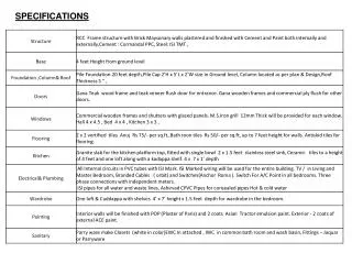
XP12000 site prep guide • Use the XP12000 Site Prep Guide from the Web (not available before products are officially released) • It has the latest specifications • Do not use notes • Be sure to cover • Physical specifications (space and weight) • Power (voltage, line current, plugs, connectors, etc) • Cooling (temperature and environment) • Connections (signal and power cables, LAN and modem connection) HP Restricted
XP12000 cooling • Significant heat output due to increased density (see next slide) • Many fans to move air • No condensation in or around the XP disk array must occur under any conditions • Covers are for cooling and EMI. They are to be installed except when unit is being serviced. Doors must be closed HP Restricted
XP12000 environmental requirements HP Restricted
XP12000 physical characteristics • Size • XP12000 is 78.2cm x 92.5cm x 186cm • Weight (floor-loading) • XP12000 is heavy • Fully configured XP12000 DKC is 586kg (1292 lbs.) • Fully configured XP12000 DKU is 755kg (1665 lbs.) • Unpacking • More than one person required for safety • Moving • Soft floor covering makes moving array difficult HP Restricted
XP12000 weight tables (1 of 2) *) for shipments outside US, Canada and Germany HP Restricted
XP12000 floor loading • Maximum point floor loading is 500kg (1102.3 lbs) • Minimum service access • Rear: 800mm (31.5 inches) • Side: 0mm • Front: 800mm (31.5 inches) HP Restricted
XP12000 space requirements HP Restricted
XP12000 service clearance • The table is for a maximum configuration (DKC + 4 DKUs). • The work service clearance is the space for CE. • To prevent damage, never use this space for storage of any article. shows distance of clearing window HP Restricted
XP128 single-rack configuration XP128 Front = DKC Rear = DKU Power supplies HDU and HDDs Batteries HP Restricted 2 – 11
Power system overview HP Restricted
DC power from batteries HP Restricted
XP12000 destage mode • New power fail strategy • When AC power is interrupted, batteries will provide power to the array for one minute, then power-down as defined by one of the following two modes configured • Destage mode (not supported at first release) • Backup mode HP Restricted
XP12000 backup mode • When the power is recovered from a failure while the backup power is supplied from the battery, the array operates depending on the status of the auto power-on switch • Enable position: The subsystem is powered on automatically • Disable position: The subsystem is powered on through an operation of the power ON/OFF switch or the PCI HP Restricted
XP12000 batteries DKC Front Battery switch Battery HP Restricted
XP12000 power (1 of 2) • Each DKU and DKU has dual-power cables for redundancy • 30A, single-phase power uses four power cables • Ideally, the customer has access to a second power grid • A UPS subsystem is highly recommended for one of the AC connections HP Restricted
XP12000 power (2 of 2) • Single- and three-phase power for the XP12000 • Two power cords for each frame except 30A, single-phase power uses four power cables • The UPS option is also covered in XP12000 Site Prep Guide HP Restricted
XP12000 power requirements summary 3-phase AC input Single-phase AC input HP Restricted
XP12000 power cable connection example 9P53U2 (plug) To power distribution panel To XP12000 R&S 9C53U2 (female connector) AC boxes HP Restricted
Power cord installation (1 of 3) HP Restricted
Power cord installation (2 of 3) HP Restricted
Power cord installation (3 of 3) HP Restricted
XP12000 power-on steps (1 of 2) • Power-on the DKC or R1 DKU breakers and other DKUs, if installed. • Turn-on the circuit breaker at the DKC power supply (PS) and the DKU PS. • Switch-on DKC and DKU batteries. • On the front panel, push the Enable switch towards Enable, and push the Power-on switch at the same time. • At the operators control panel, look for • BS-on LEDs • PS-on LED • Local switch • After the array has powered-up, verify the configuration. HP Restricted
XP12000 power-on steps (2 of 2) • Run Path Inlines. • If necessary, reconfigure the array groups. • Configure and install any upgrades which were not included with the system. • Follow the SVP procedures which are listed in the XP Array Maintenance Manual, section INST05-20. • Configure LDEVs and host hardware paths, using your configuration map. HP Restricted
Learning check HP Restricted
Learning check HP Restricted
Lab activity HP Restricted