Download
1 / 24
250 likes | 271 Views
High Level Physics Applications for LCLS Commissioning. Henrik Loos. Physics Applications Overview. Matlab framework for development ~35 applications developed by physicists ~30 with graphical user interfaces (GUIs) Created and grown within last year

E N D
High Level Physics Applications for LCLS Commissioning Henrik Loos
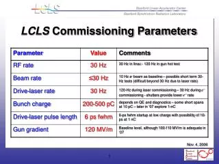
Physics Applications Overview • Matlab framework for development • ~35 applications developed by physicists • ~30 with graphical user interfaces (GUIs) • Created and grown within last year • Development driven by commissioning needs • Quick adoption of new features
Diagnostics Profile Monitors Wire Scanners Emittance Bunch Length Correlation Plot Cathode QE Laser Pulse Length Orbit Response Status Displays Operating Point Orbit RF Status Beam Jitter Beam Images Machine Control & Tuning Beam Line Switching Bunch Compressor Control Twiss Matching Undulator Beam Based Alignment Simulation LiTrack 1D FEL Code Application Types
Operating Point • Primary definition for main machine parameters • Used as defaults for other applications • Electronic checklist • Compares actuals with set points • No machine control H.-D. Nuhn
Linac Beam Jitter • Measures transverse beam jitter in injector and near end of linac • Display of jitter in terms of normalized phase space • Display of energy jitter thoughout machine D. Ratner
RF Phase Scans • Beam based measurement of all RF phases • Integrates Epics and SCP controls • Amplitude calibration and phase re-golding • Stores results in PVs for archiving P. Emma
Twiss Parameter Matching • Gets Twiss from previous emittance measurement • Wire scanner or profile monitor • Applies solution to magnet settings • Will include undulator matching soon C. Limborg
Dispersion Measurement P. Emma • Orbit measurement after chicanes with varying beam energy • Calculates resulting emittance growth and corrector quad strengths • Applies correction
Bunch Compressor Control • Set R56 of chicane • Controls • Dipole strengths • Chicane motion • Matching quads • Upstream RF phases P. Emma
Beam Diagnostics Application Hierarchy Correlation Plot Bunch Length Emittance Profile Monitor Wire Scan
Common User Interface Features Files Configs Measure Export Data Point
Image Acquisition • Live image display • Pixels or calibrated display • Line outs • Intensity histogram • Fit results • Interactive screen calibration
Wire Scans • Beam synchronous acquisition of wire position, PMT signals, charge, and beam position • Automatic set of scan range from BPM reading • Optional jitter correction and charge normalization • Applies set of fit algorithms to profiles • Add support for undulator beam finder wires
Bunch Length Measurement • Measures bunch length at various profile monitors using TCAV0 and 3 • Scans TCAV phase for calibration. • Plot of measured images, profiles, and beam size fit.
Emittance GUI Features • Measures emittance at various profile monitors and wire scanners. • Uses quadrupole scan or acquisition at multiple locations (multi screen). • Projected emittance or slice emittance • Sets PVs for archiving and matching • Plot of measured profiles, beam size fit, and phase space view. • Add emittance measurement using undulator beam finder wires.
Correlation Plot Features • Scans any epics process variable (PV) • Measures multiple samples of any number of PVs • Non-synchronous and synchronous acquisition • Scan of 2 PVs for 2-D plots • Scan of SLC magnets • Time scan • Measurement of emittance, bunch length, profile monitors, wire scanners • Selection of different fit functions • Plot of selected results
Applications for Next Phase • Beam-Based Alignment of the FEL Undulator - (Loos) • Undulator Steering and re-Pointing - (Nuhn) • K-measurement Application - (Welch/Emma/Nuhn) • Beam-Finder Wire Application - Centering & Emittance - (Loos/Nuhn?) • LTU Emittance Measurement - (Loos - extension of existing GUI) • Beta-Matching into undulator - (Limborg - extension of existing GUI) • FEE diagnostics - (see R. Bionta's talk)
Undulator Beam Based Alignment Measurement of undulator orbit at 3+ energies Fit of BPM & quad offsets and orbit Changes BPM offsets Moves quads with undulator girders Launches beam into undulator Integrates simulation Orbit Preliminary Simulation Offsets Measurement
Modified BL21 Interference Signal Detectors Detectors Sum Signal Filters Filters Paraboloid Paraboloid Splitters Splitter Mirrors Radiation Radiation FTIR Spectrometer for Micro Bunching Studies Existing BL21 Layout
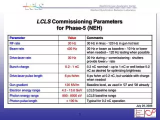
Spectrometer Details • Upgrade for BL21 Edge radiation monitor after BC2 • Compatible with present use • At center position, both detectors see the same intensities as presently • Resolution • Scan range L = 10mm • Step size ΔL = 5μm • Δν = 1/(2L) = 0.5 cm-1 • νmax = 1/4ΔL = 250 cm-1 • Spectral range = [20μm – 20mm] • Issues • Converging beam in spectrometer • Different phase front curvature will suppress interference
Summary • Migration of applications from physicists to software group • Matlab applications were developed in interaction with control room needs • Existing Matlab applications are used to define software requirements • Gradual replacement from lower level apps (e.g. wire scan) to highest level (e.g. correlation plots)