Download
1 / 13
130 likes | 225 Views
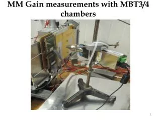
This study aims to measure the gain in MBT3/4 chambers for ATLAS during the 2012 run with an Ag Mini X-Ray Gun. Gain is measured as a function of HV, and estimates are made for primary electrons generated by the X-Ray flux. The setup includes a Gas Distribution 2D Readout system, with HV applied using APV cards. Gain measurements are conducted for both MBT3 and MBT4 chambers, with analysis of true and noise clusters. The study identifies uncertainties in incoming charge estimation and differences in gain between chambers. Further investigations into environmental effects and comparisons with Cu X-Ray gun measurements are planned.

E N D
By using an MiniX-Ray Gun (Ag), we want to measure the gain in the MBT3 and MBT4 chambers used in ATLAS during 2012 run. • The X-Ray generated by the MiniX-Ray system are more penetrating than the X-Ray produced by the Cu X-Ray gun, this allow us to measure the gain of the MBT3/4 at the same time under different X-Ray flux conditions but with the same environmental conditions. • We need to estimate the rate of the “primary electrons” generate by the flux of the incoming X-Ray. • The MMs gain is measured as a function of the HV. MM Gain measurements with MBT3/4 chambers
MBT chambers layout Gas Distribution 2D Readout system, X and V coordinate Common Drift Electrode HV 9 mm 2 APV card used for each MBT chamber (256 channels). Channels map organized in order to reconstruct X coordinate from 1-200 ch. and Vch. from 201 to 256. 4.5 mm 4.5 mm
X-Ray / MM chamber setup MM HV Side
MBT3/4 Scanning conditions • The chambers were scanned using the MiniX-Ray gun. • To apply HV on the resistive strips and the drift, the CAEN SY2527 and A1821 boards were used. X-Ray gun: HV = 30.00kV Beam intensity = 12 microA HV-resistive strips = +450 to +550V HV-drift = -300V (monitored by power supply) • Two HV scans have been performed with MBT3 or MBT4 in front of the X-Ray gun.
Collected Data 100 K events for each run Total readout window for run 0.0675 s
Amplification Current Vs HV MBT4 in front to the X-Ray Gun MBT3 in front to the X-Ray Gun
Gain Measurements G = Cf/ Ci For a single event we define the GAIN as follow: Cf = Final Charge Ci = Initial Charge We can extract the total Final Charge from the current delivered by the power supply. The number of reconstructed clusters (per second) gives us the rate of the converted X-Ray From each converted X-Ray we expect ~ 500 electrons (13 KeV / 26 eV)
Initial Cluster selection “ True” Clusters Applied cut “clqmax>100” and Cluster size > 1, to remove noise clusters “ True” Clusters “ Noise” Clusters
Initial Cluster selection MBT3 far from the X-Ray gun MBT4 close to the X-Ray gun
Initial Cluster selection MBT3 close to the X-Ray gun MBT4 far from the X-Ray gun
Chamber Gain Vs HV MBT4 close to the X-Ray gun MBT3 close to the X-Ray gun
Summary • A first MM gain measurement, using Ag Mini X-Ray system as been done with MBT3/4 chamber. • First source of uncertainty for this measure come from the incoming charge estimation: • Number of conversion for second. • Number of “primary” electrons for each conversion. • A small difference of gain, equivalent to 10 Volts, seems to be present between MBT3/MBT4 ( the effect is more evident in the second scan). • The gain has not been corrected for the possible HV drop as a consequence of the high current generate by the high flux and for environmental variations between the two different scans. • Same measurements can be performed with Cu X-Ray gun, in this case we can study only one chamber for each scan. • Next steps: • Evaluation of the voltage drop effect on. • Gain measurements and characterizationas a function of the environmental conditions. • Gain measurements for T and L chambers.