Download
1 / 41
420 likes | 552 Views
Introduction to Routing and Packet Forwarding. Routing Protocols and Concepts – Chapter 1. Objectives. Identify a router as a computer with an OS and hardware designed for the routing process. Demonstrate the ability to configure devices and apply addresses.

E N D
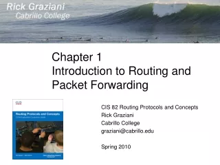
Introduction to Routing and Packet Forwarding Routing Protocols and Concepts – Chapter 1
Objectives • Identify a router as a computer with an OS and hardware designed for the routing process. • Demonstrate the ability to configure devices and apply addresses. • Describe the structure of a routing table. • Describe how a router determines a path and switches packets.
Router as a Computer • Describe the basic purpose of a router • Computers that specialize in sending packets over the data network • They are responsible for interconnecting networks by selecting the best path for a packet to travel and forwarding packets to their destination • Routers are the network center • Routers generally have 2 connections: • WAN connection (Connection to ISP) • LAN connection
Router as a Computer • Data is sent in form of packets between 2 end devices • Routers are used to direct packet to its destination
Router as a Computer • Routers examine a packet’s destination IP address and determine the best path by enlisting the aid of a routing table
Router as a Computer • Router components and their functions: • CPU - Executes operating system instructions • Random access memory (RAM) - Contains the running copy of configuration file. Stores routing table. RAM contents lost when power is off. • Read-only memory (ROM) - Holds diagnostic software used when router is powered up. Stores the router’s bootstrap program. • Non-volatile RAM (NVRAM) - Stores startup configuration. This may include IP addresses (Routing protocol, Hostname of router). • Flash memory - Contains the operating system (Cisco IOS). • Interfaces - There exist multiple physical interfaces that are used to connect network. Examples of interface types: • Ethernet / fast Ethernet interfaces • Serial interfaces • Management interfaces
Router as a Computer • Router components
Router as a Computer • Major phases to the router boot-up process • Test router hardware • Power-On Self Test (POST) • Execute bootstrap loader • Locate & load Cisco IOS software • Locate IOS • Load IOS • Locate & load startup configuration file or enter setup mode • Bootstrap program looks for configuration file
Router as a Computer • Verify the router boot-up process: • The show version command is used to view information about the router during the bootup process. Information includes: • Platform model number • Image name & IOS version • Bootstrap version stored in ROM • Image file name & where it was loaded from • Number & type of interfaces • Amount of NVRAM • Amount of flash • Configuration register
Router as a Computer • Router Interface is a physical connector that enables a router to send or receive packets • Each interface connects to a separate network • Consist of socket or jack found on the outside of a router • Types of router interfaces: • Ethernet • Fastethernet • Serial • DSL • ISDN • Cable
Router as a Computer • Two major groups of Router Interfaces • LAN Interfaces • Are used to connect router to LAN network • Has a layer 2 MAC address • Can be assigned a Layer 3 IP address • Usually consist of an RJ-45 jack • WAN Interfaces • Are used to connect routers to external networks that interconnect LANs • Depending on the WAN technology, a layer 2 address may be used • Uses a layer 3 IP address
Router as a Computer • Routers and the Network Layer • Routers use destination IP address to forward packets • The path a packet takes is determined after a router consults information in the routing table • After router determines the best path • Packet is encapsulated into a frame • Frame is then placed on network medium in form of Bits
Router as a Computer • Routers Operate at Layers 1, 2 & 3 • Router receives a stream of encoded bits • Bits are decoded and passed to layer 2 • Router de-encapsulates the frame • Remaining packet passed up to layer 3 • Routing decision made at this layer by examining destination IP address • Packet is then re-encapsulated & sent out outbound interface
Configure Devices and Apply Addresses • Implementing Basic Addressing Schemes • When designing a new network or mapping an existing network you must provide the following information in the form of a document: • Topology drawing that Illustrates physical connectivity • Address table that provides the following information: • Device name • Interfaces used • IP addresses • Default gateway
Configure Devices and Apply Addresses • Basic Router Configuration • A basic router configuration should contain the following: • Router name - Host name should be unique. • Banner - At a minimum, banner should warn against unauthorized use. • Passwords - Use strong passwords. • Interface configurations - Specify interface type, IP address and subnet mask. Describe purpose of interface. Issue no shutdown command. If DCE serial interface issue clock rate command. • After entering in the basic configuration the following tasks should be completed: • Verify basic configuration and router operations. • Save the changes on a router.
Configure Devices and Apply Addresses • Verify Basic Router Configuration • Issue the show running-config command • Save the basic router configuration by issuing the copy running-config startup-config command • Additional commands that will enable you to further verify router configuration are: • Show running-config - Displays configuration currently in RAM • Show startup-config - Displays configuration file NVRAM • Show IP route - Displays routing table • Show interfaces - Displays all interface configurations • Show IP int brief - Displays abbreviated interface configuration information
Routing Table Structure • Routing Table is stored in ram and contains information about: • Directly connected networks - this occurs when a device is connected to another router interface • Remotely connected networks - this is a network that is not directly connected to a particular router • Detailed information about the networks include source of information, network address & subnet mask, and Ip address of next-hop router • Show ip route command is used to view a routing table
Routing Table Structure • Adding a connected network to the routing table • Router interfaces • Each router interface is a member of a differentnetwork • Activated using the no shutdown command • In order for static and dynamic routes to exist in routing table you must have directly connected networks
Routing Table Structure • Static routes in the routing table • Includes: network address and subnet mask and IP address of next hop router or exit interface • Denoted with the code Sin the routing table • Routing tables must contain directly connected networks used to connect remote networks before static or dynamic routing can be used • When to use static routes • When network only consists of a few routers • Network is connected to internet only through one ISP • Hub & spoke topology is used on a large network
Routing Table Structure • Connected and Static routes
Routing Table Structure • Dynamic routing protocols • Used to add remote networks to a routing table • Are used to discover networks • Are used to update and maintain routing tables • Automatic network discovery • Routers are able discover new networks by sharing routing table information
Routing Table Structure • Maintaining routing tables • Dynamic routing protocols are used to share routing information with other router & to maintain and up date their own routing table • IP routing protocols - example of routing protocols include: • RIP • IGRP • EIGRP • OSPF
Routing Table Structure • Routing Table Principles • 3 principles regarding routing tables: • Every router makes its decisions alone, based on the information it has in its routing table • Different routing table may containdifferentinformation • A routing table can tell how to get to a destination but not how to get back
Routing Table Structure • Effects of the 3 Routing Table Principles • Packets are forwarded through the network from one router to another, on a hop by hop basis • Packets can take path “X” to a destination but return via path “Y” (Asymmetric routing)
Router Paths and Packet Switching • Internet Protocol (IP) packet format contains fields that provide information about the packet and the sending and receiving hosts • Fields that are importance for CCNA students: • Destination IP address • Source IP address • Version & TTL • IP header length • Precedence & type of service • Packet length
Router Paths and Packet Switching • MAC Layer Frame Format • MAC Frames are also divided into fields - they include: • Preamble • Start of frame delimiter • Destination MAC address • Source MAC address • Type/length • Data and pad • Frame check sequence
Router Paths and Packet Switching • A Metric is a numerical value used by routing protocols help determine the best path to a destination • The smaller the metric value the better the path • 2 types of metrics used by routing protocols are: • Hop count - this is the number of routers a packet must travel through to get to its destination • Bandwidth - this is the “speed” of a link also known as the data capacity of a link
Router Paths and Packet Switching • Equal cost metric is a condition where a router has multiple paths to the same destination that all have the same metric • To solve this dilemma, a router will useEqual Cost Load Balancing - this means the router sends packets over the multiple exit interfaces listed in the routing table.
Router Paths and Packet Switching • Path determination is a process used by a router to pick the best path to a destination • One of 3 path determinations results from searching for the best path • Directly connected network • Remote network • No route determined
Router Paths and Packet Switching • Switching Function of Router is the process used by a router to switch a packet from an incoming interface to an outgoing interface on the same router • A packet received by a router will do the following: • Strips off layer 2 headers • Examines destination IP address located in Layer 3 header to find best route to destination • Re-encapsulates layer 3 packet into layer 2 frame • Forwards frame out exit interface
Router Paths and Packet Switching • As a packet travels from one networking device to another • The Source and Destination IP addressesNEVER change • The Source & Destination MAC addresses CHANGE as packet is forwarded from one router to the next • TTL field decrement by one until a value of zero is reached at which point router discards packet (prevents packets from endlessly traversing the network)
Router Paths and Packet Switching • Path determination and switching function details. PC1 wants to send something to PC 2. • Step 1 - PC1 encapsulates packet into a frame - frame contains R1’s destination MAC address
Router Paths and Packet Switching • Step 2 - R1 receives Ethernet frame • R1 sees that destination MAC address matches its own MAC • R1 then strips off Ethernet frame • R1 Examines destination IP • R1 consults routing table looking for destination IP • After finding destination IP in routing table, R1 now looks up next hop IP address • R1 re-encapsulates IP packet with a new Ethernet frame • R1 forwards Ethernet packet out Fa0/1 interface
Router Paths and Packet Switching • Step 3 - Packet arrives at R2 • R2 receives Ethernet frame • R2 sees that destination MAC address matches its own MAC • R2 then strips off Ethernet frame • R2 Examines destination IP • R2 consults routing table looking for destination IP • After finding destination IP in routing table, R2 now looks up next hop IP address • R2 re-encapsulates IP packet with a new data link frame • R2 forwards Ethernet packet out S0/0 interface
Router Paths and Packet Switching • Step 4 - Packet arrives at R3 • R3 receives PPP frame • R3 then strips off PPP frame • R3 Examines destination IP • R3 consults routing table looking for destination IP • After finding destination IP in routing table, R3 is directly connected to destination via its fast Ethernet interface • R3 re-encapsulates IP packet with a new Ethernet frame • R3 forwards Ethernet packet out Fa0/0 interface • Step 5 - IP packet arrives at PC2 - frame is decapsulated and processed by upper layer protocols
Summary • Routers are computers that specialize in sending data over a network. • Routers are composed of: • Hardware i.e. CPU, Memory, System bus, Interfaces • Software used to direct the routing process • IOS • Configuration file • Routers need to be configured. Basic configuration consists of: • Router name • Router banner • Password(s) • Interface configurations i.e. IP address and subnet mask • Routing tables contain the following information: • Directly connected networks • Remotely connected networks • Network addresses and subnet masks • IP address of next hop address
Summary • Routers determine a packets path to its destination by the following: • Receiving an encapsulated frame & examining destination MAC address. • If the MAC address matches then Frame is de-encapsulated so that router can examine the destination IP address. • If destination IP address is in routing table or there is a static route then Router determines next hop IP address. Router will re-encapsulate packet with appropriate layer 2 frame and send it out to next destination. • Process continues until packet reaches destination. • Note - only the MAC addresses will change the source and destination IP addresses do not change.