Download

1 / 100
1.03k likes | 1.24k Views
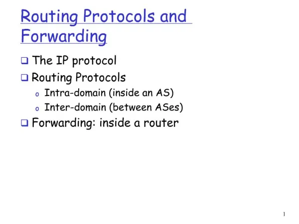
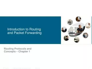
Introduction to Routing and Packet Forwarding. Routing Protocols and Concepts – Chapter 1 Modified by Mike Haines. 10/14/2010. Objectives. Identify a router as a computer with an OS and hardware designed for the routing process.

E N D
Introduction to Routing and Packet Forwarding Routing Protocols and Concepts – Chapter 1 Modified by Mike Haines 10/14/2010
Objectives • Identify a router as a computer with an OS and hardware designed for the routing process. • Demonstrate the ability to configure devices and apply addresses. • Describe the structure of a routing table. • Describe how a router determines a path and switches packets
Router as a Computer • Describe the basic purpose of a router -Computers that specialize in sending packets over the data network. They are responsible for interconnecting networks by selecting the best path for a packet to travel and forwarding packets to their destination • Routers have many of the same hardware and software components that are found in other computers including: • CPU • RAM • ROM • Operating System
Router as a Computer • Router components and their functions” • CPU - Executes operating system instructions • such as system initialization, routing functions, and switching functions. • Random access memory (RAM) -RAM stores the instructions and data needed to be executed by the CPU. RAM is used to store these components: • Operating System: The Cisco IOS (Internetwork Operating System) is copied into RAM during bootup. • Running Configuration File: This is the configuration file that stores the configuration commands that the router IOS is currently using. • IP Routing Table: This file stores information about directly connected and remote networks. It is used to determine the best path to forward the packet. • ARP Cache: This cache contains the IPv4 address to MAC address mappings, similar to the ARP cache on a PC. The ARP cache is used on routers that have LAN interfaces such as Ethernet interfaces. • Packet Buffer: Packets are temporarily stored in a buffer when received on an interface or before they exit an interface. RAM is volatile memory and loses its content when the router is powered down or restarted.
Router as a Computer • Router components and their functions” • Read-only memory (ROM) - Holds diagnostic software used when router is powered up. Stores the router’s bootstrap program. • ROM is a form of permanent storage. Cisco devices use ROM to store: • The bootstrap instructions • Basic diagnostic software • Scaled-down version of IOS ROM uses firmware, which is software that is embedded inside the integrated circuit. • Firmware includes the software that does not normally need to be modified or upgraded, such as the bootup instructions. • ROM does not lose its contents when the router loses power or is restarted.
Router as a Computer • Router components and their functions” • Non-volatile RAM (NVRAM) - Stores startup configuration. This may include IP addresses (Routing protocol, Hostname of router) • NVRAM (Nonvolatile RAM) does not lose its information when power is turned off. This is in contrast to the most common forms of RAM, such as DRAM, that requires continual power to maintain its information. • NVRAM is used by the Cisco IOS as permanent storage for the startup configuration file. • All configuration changes are stored in the running-config file in RAM, and with few exceptions, are implemented immediately by the IOS. • To save those changes in case the router is restarted or loses power, the running-config must be copied to NVRAM, where it is stored as the startup-config file. NVRAM retains its contents even when the router reloads or is powered off. • Flash memory - Contains the operating system (Cisco IOS) • In most models of Cisco routers, the IOS is permanently stored in flash memory and copied into RAM during the bootup process, where it is then executed by the CPU. • Flash consists of SIMMs or PCMCIA cards, which can be upgraded to increase the amount of flash memory. • Interfaces - There exist multiple physical interfaces that are used to connect network. Examples of interface types: -Ethernet / fast Ethernet interfaces -Serial interfaces -Management interfaces
Router as a Computer • Router components
Internetwork Operating System • The operating system software used in Cisco routers is known as Cisco Internetwork Operating System (IOS). • Cisco IOS is a multitasking operating system that is integrated with routing, switching, internetworking, and telecommunications functions. • Although the Cisco IOS may appear to be the same on many routers, there are many different IOS images. • An IOS image is a file that contains the entire IOS for that router. Cisco creates many different types of IOS images, depending upon the model of the router and the features within the IOS. • Typically the more features in the IOS, the larger the IOS image, and therefore, the more flash and RAM that is required to store and load the IOS. • Although some routers provide a graphical user interface (GUI), the command line interface (CLI) is a much more common method of configuring Cisco routers. • The CLI is used throughout this curriculum. • Upon bootup, the startup-config file in NVRAM is copied into RAM and stored as the running-config file. • IOS executes the configuration commands in the running-config. Any changes entered by the network administrator are stored in the running-config and are immediately implemented by the IOS.
Router as a Computer • Major phases to the router boot-up process • Test router hardware Power-On Self Test (POST) Execute bootstrap loader • Locate & load Cisco IOS software -Locate IOS -Load IOS • Locate & load startup configuration file or enter setup mode -Bootstrap program looks for configuration file
Router as a Computer • Major phases to the router boot-up process Step 1 and 2: Test router hardware • Power-On Self Test (POST) • During this self-test, the router executes diagnostics from ROM on several hardware components including the CPU, RAM, and NVRAM • Execute bootstrap loader • The main task of the bootstrap program is to locate the Cisco IOS and load it into RAM. • Note: At this point, if you have a console connection to the router, you will begin to see output on the screen. Step 3 and 4: Locate & load Cisco IOS software -Locate IOS and Load IOS • The IOS is typically stored in flash memory, but can also be stored in other places such as a TFTP server. • If a full IOS image can not be located, a scaled-down version of the IOS is copied from ROM into RAM. This version of IOS is used to help diagnose any problems and can be used to load a complete version of the IOS into RAM. • Note: A TFTP server is usually used as a backup server for IOS but it can also be used as a central point for storing and loading the IOS.
Router as a Computer Step 5 and 6: Locate & load startup configuration file or enter setup mode -After the IOS is loaded, the bootstrap program searches for the startup configuration file, known as startup-config, in NVRAM. This parameters including: • interface addresses • routing information • passwords • any other configurations • If the startup-config, is located in NVRAM, it is copied into RAM as the running-config. • The IOS loads the commands in the file, one line at a time. • If the startup configuration file does not exist in NVRAM, the router may search for a TFTP server. • If the router detects that it has an active link to another configured router, it sends a broadcast searching for a configuration file across the active link. You will eventually see message like the following one: • %Error opening tftp://255.255.255.255/network-confg (Timed out) • %Error opening tftp://255.255.255.255/cisconet.cfg (Timed out)
Router as a Computer • Locate & load startup configuration file or enter setup mode • Enter Setup Mode (Optional). If the startup configuration file can not be located, the router prompts the user to enter setup mode. • Setup mode is a series of questions prompting the user for basic configuration information. Setup mode is not intended to be used to enter complex router configurations, and it is not commonly used by network administrators. • When booting a router that does not contain a startup configuration file, you will see the following question after the IOS has been loaded: • Would you like to enter the initial configuration dialog? [yes/no]: no • Setup mode will not be used in this course to configure the router. When prompted to enter setup mode, always answer no. If you answer yes and enter setup mode, you can press Ctrl-C at any time to terminate the setup process. • When setup mode is not used, the IOS creates a default running-config. • The default running-config is a basic configuration file that includes the router interfaces, management interfaces, and certain default information. • The default running-config does not contain any interface addresses, routing information, passwords, or other specific configuration information.
Router as a Computer show version • Verify the router boot-up process: -The show version command is used to view information about the router during the bootup process. Information includes: • Image name & IOS version IOS (tm) C2600 Software (C2600-I-M), Version 12.2(28), RELEASE SOFTWARE (fc5). • Bootstrap version stored in ROM • ROM: System Bootstrap, Version 12.1(3r)T2, RELEASE SOFTWARE (fc1) • Image file name & where it was loaded from • System image file is "flash:c2600-i-mz.122-28.bin"
Router as a Computer show version • Verify the router boot-up process: • Platform model number • CPU • Amount of RAM • Some series of routers, like the 2600, use a fraction of DRAM as packet memory. Packet memory is used for buffering packets. • To determine the total amount of DRAM on the router, add both numbers. In this example, the Cisco 2621 router has 60,416 KB (kilobytes) of free DRAM used for temporarily storing the Cisco IOS and other system processes. The other 5,120 KB is dedicated for packet memory. The sum of these numbers is 65,536K, or 64 megabytes (MB) of total DRAM.
Router as a Computer show version • Verify the router boot-up process: • Number & type of interfaces 2 FastEthernet/IEEE 802.3 interface(s) 2 Low-speed serial(sync/async) network interface(s) • Amount of NVRAM • 32K bytes of non-volatile configuration memory. • NVRAM is used to store the startup-config file. • Amount of flash • 16384K bytes of processor board System flash (Read/Write) • This is the amount of flash memory on the router. Flash is used to permanently store the Cisco IOS.
Router as a Computer show version • Configuration register • Configuration register is 0x2102 • The last line of the show version command displays the current configured value of the software configuration register in hexadecimal. If there is a second value displayed in parentheses, it denotes the configuration register value that will be used during the next reload. • The configuration register has several uses, including password recovery. The factory default setting for the configuration register is 0x2102. This value indicates that the router will attempt to load a Cisco IOS software image from flash memory and load the startup configuration file from NVRAM. • Note: The configuration register is discussed in more detail in a later course.
Configuration register • The order in which the router looks for system bootstrap depends on the boot field setting in the configuration register. The default configuration register setting can be changed with the global configuration mode command config-register. Use a hexadecimal number as the argument for this command. • The configuration register is a 16-bit register in NVRAM. The lowest four bits of the configuration register form the boot field. To ensure that the upper 12 bits are not changed, first retrieve the current values of the configuration register using the show version command. Then use the config-register command, changing only the value of the last hexadecimal digit.
Configuration register (cont.) • To enter the ROM monitor mode, set the configuration register value to 0xnnn0, where nnn represents the previous value of the non-boot field digits. This value sets the boot field bits to 0000 binary. From ROM monitor, boot the operating system manually by using the b command at the ROM monitor prompt. • To configure the system to boot automatically from ROM, set the configuration register to 0xnnn1, This value sets the boot field bits to 0001 binary. • To configure the system to use the boot system commands in NVRAM, set the configuration register to any value from 0xnnn2 to 0xnnnF, These values set the boot field bits to a value between 0010 and 1111 binary. Using boot system commands in NVRAM is the default. Check Configuration Register value (NVRAM) 0 = ROM Monitor mode 1 = ROM IOS 2 - 15 = Boot system from Flash
How a Cisco device locates and loads IOS The config-register can be Downloaded from: http://www.lilligren.com/cisco/downloads.htm • Demo config-register
Configuration register Router(config)#config-register value 1 2 3
Stages of the router power-on boot sequence 1. ROM 1. POST 2. Bootstrap code executed 3. Check Configuration Register value (NVRAM) 0 = ROM Monitor mode 1 = ROM IOS 2 - 15 = Boot system from flash 2.Check for IOS boot system commands in startup-config file (NVRAM) If boot system commands in startup-config a. Run boot system commands in order they appear in startup-config to locate the IOS b If boot system commands fail, use default fallback sequence to locate the IOS (Flash, TFTP, ROM) 3.Locate and load IOS, Default fallback sequence: No IOS boot system commands in startup-config a. Flash (sequential) b. TFTP server (netboot) - The router uses the configuration register value to form a filename from which to boot a default system image stored on a network server. c. ROM (partial IOS) or keep retrying TFTP depending upon router model - If no IOS located, get partial IOS version from ROM 4.Locate and load startup-config a. If startup-config found, copy to running-config b. If startup-config not found, prompt for setup-mode c. If setup-mode bypassed, create a “skeleton” default running-config (no startup-config) 1, 2 3 4
How a Cisco device locates and loads IOS • The router can use its own fallback sequence to load the software. The router looks to the boot system commands saved in NVRAM. (Tony) The router has its own default fallback sequence. This default sequence can be interrupted by using the boot system command and/or config register. • The settings in the configuration register enable the following alternatives: Global configuration mode boot system commands can be specified to enter fallback sources. If NVRAM lacks boot system commands the system by default uses the Cisco IOS software in flash memory. (Tony) No boot system commands (Tony) IOS specified in the boot system does not exist If flash memory is empty, the router then attempts to use TFTP to load an IOS image from the network.
Using the boot system command • The three examples show boot system entries which specify that a Cisco IOS software image will load First from flash memory, Flash memory – A system image from flash memory can be loaded. Then from a network server, and Network server – In case flash memory becomes corrupted, a system image can be loaded from a TFTP server. Finally from ROM: ROM – If flash memory is corrupted and the network server fails to load the image, booting from ROM is the final bootstrap option in software. However, the system image in ROM is a subset of the Cisco IOS that lacks the protocols, features of the full Cisco IOS. Also, if the software has been updated, the router may have an older version stored in ROM. • The command copy running-config startup-config saves the commands in NVRAM.
How a Cisco device locates and loads IOS • What happen when both config-register and boot • system both exist in the startup-config? • Which one has the priority?
Management Ports • Routers have physical connectors that are used to manage the router. These connectors are known as management ports. • Unlike Ethernet and serial interfaces, management ports are not used for packet forwarding. • The most common management port is the console port. • The console port is used to connect a terminal, or most often a PC running terminal emulator software, to configure the router without the need for network access to that router. • The console port must be used during initial configuration of the router. • Another management port is the auxiliary port. • Not all routers have auxiliary ports. • At times the auxiliary port can be used in ways similar to a console port. It can also be used to attach a modem. • Auxiliary ports will not be used in this curriculum.
Routers determine the best path • Router Interface is a physical connector that enables a router to send or receive packets • Each interface connects to a separate network • different IP network • Typically, the interfaces connect to various types of networks, which means that different types of media and connectors are required. Types of router interfaces: -Ethernet -Fastethernet -Serial -DSL -ISDN -Cable
Two major groups of Router Interfaces: LAN & WAN • LAN Interfaces: such as Ethernet and FastEthernet • Are used to connect router to LAN network • Has a layer 2 MAC address • a router Ethernet interface participates in the ARP process for that LAN. • Can be assigned a Layer 3 IP address • Usually consist of an RJ-45 jack • When a router is connected to a switch, a straight-through cable is used. • When two routers are connected directly through the Ethernet interfaces, or when a PC NIC is connected directly to a router Ethernet interface, a crossover cable is used.
Two major groups of Router Interfaces: LAN & WAN • WAN Interfaces-such as serial, ISDN, and Frame Relay • Are used to connect routers to external networks that interconnect LANs, usually over a larger geographical distance.. • Depending on the WAN technology, a layer 2 address may be used. • Uses a layer 3 IP address • Similar to LAN interfaces, each WAN interface has its own IP address and subnet mask, which identifies it as a member of a specific network. • The Layer 2 encapsulation can be of different types, • PPP, Frame Relay, and HDLC (High-Level Data Link Control).
Two major groups of Router Interfaces: LAN & WAN • The router in the figure has four interfaces. • Each interface has a Layer 3 IP address and subnet mask that configures it for a different network. • The Ethernet interfaces also have Layer 2 Ethernet MAC addresses. • The WAN interfaces are using different Layer 2 encapsulations. • Serial 0/0/0 is using HDLC • Serial 0/0/1 is using PPP. • Both of these serial point-to-point protocols use a broadcast address for the Layer 2 destination address when encapsulating the IP packet into a data link frame.
Routers determine the best path • A router connects multiple networks. • This means that it has multiple interfaces that each belong to a different IP network. • When a router receives an IP packet on one interface, it determines which interface to use to forward the packet onto its destination. • The interface that the router uses to forward the packet may be the network of the final destination of the packet (the network with the destination IP address of this packet), or it may be a network connected to another router that is used to reach the destination network. • Routers are the network center -Routers generally have 2 connections: -WAN connection (Connection to ISP) -LAN connection
Routers determine the best path • Routers examine a packet’s destination IP address and determine the best path by enlisting the aid of a routing table
Routers determine the best path • The primary responsibility of a router is to direct packets destined for local and remote networks by: • Determining the best path to send packets • Forwarding packets toward their destination • The router uses its routing table to determine the best path to forward the packet. • When the router receives a packet, it examines its destination IP address and searches for the best match with a network address in the router's routing table. • The routing table also includes the interface to be used to forward the packet. Once a match is found, the router encapsulates the IP packet into the data link frame of the outgoing or exit interface, and the packet is then forwarded toward its destination. • It is very likely that a router will receive a packet that is encapsulated in one type of data link frame, such as an Ethernet frame and when forwarding the packet, the router will encapsulate it in a different type of data link
Routers determine the best path • Routers Operate at Layers 1, 2 & 3 • A router makes its primary forwarding decision at Layer 3, but as we saw earlier, it participates in Layer 1 and Layer 2 processes as well. • Router receives a stream of encoded bits • Bits are decoded and passed to layer 2 • Router de-encapsulates the frame • Remaining packet passed up to layer 3 -Routing decision made at this layer by examining destination IP address • Packet is then re-encapsulated & sent out outbound interface
Routers determine the best path • PC1 operates at all seven layers, encapsulating the data and sending the frame out as a stream of encoded bits to R1, its default gateway. • R1 receives the stream of encoded bits on its interface. The bits are decoded and passed up to Layer 2, where R1 decapsulates the frame. The router examines the destination address of the data link frame to determine if it matches the receiving interface, including a broadcast or multicast address. If there is a match with the data portion of the frame, the IP packet is passed up to Layer 3, where R1 makes its routing decision. R1 then re-encapsulates the packet into a new Layer 2 data link frame and forwards it out the outbound interface as a stream of encoded bits. • R2 receives the stream of bits, and the process repeats itself. R2 decapsulates the frame and passes the data portion of the frame, the IP packet, to Layer 3 where R2 makes its routing decision. R2 then re-encapsulates the packet into a new Layer 2 data link frame and forwards it out the outbound interface as a stream of encoded bits. • This process is repeated once again by router R3, which forwards the IP packet, encapsulated inside a data link frame and encoded as bits, to PC2.
Configure Devices and Apply Addresses • Implementing Basic Addressing Schemes • When designing a new network or mapping an existing network you must provide the following information in the form of a document: -Topology drawing that Illustrates physical connectivity • Address table that provides the following information: • Device name • Interfaces used • IP addresses • Default gateway
Configure Devices and Apply Addresses • Basic Router Configuration • A basic router configuration should contain the following: -Router name - Host name should be unique -Banner - At a minimum, banner should warn against unauthorized use -Passwords - Use strong passwords -Interface configurations – • Specify interface type, • IP address and subnet mask. • Describe purpose of interface. • Issue no shutdown command. • If DCE serial interface issue clock rate command. • After entering in the basic configuration the following tasks should be completed -Verify basic configuration and router operations. -Save the changes on a router
Configure Devices and Apply Addresses brief review from CCNA1 Router> Router>enable Router# Router#config t Router(config)#enable secret class Router(config)#enable password cisco Router(config)#hostname R1 R1(config)# R1(config)#line console 0 R1(config-line)#password cisco R1(config-line)#login R1(config-line)#exit R1(config)#line vty 0 4 R1(config-line)#password cisco R1(config-line)#login R1(config-line)#exit
Configure Devices and Apply Addresses brief review from CCNA1 Configuring a Banner From the global configuration mode, configure the message-of-the-day (motd) banner. A delimiting character, such as a "#" is used at the beginning and at the end of the message. The delimiter allows you to configure a multiline banner, as shown here. R1(config)#banner motd # Enter TEXT message. End with the character '#'. ****************************************** WARNING!! Unauthorized Access Prohibited!! ****************************************** # Configuring an appropriate banner is part of a good security plan. At a very minimum, a banner should warn against unauthorized access. Never configure a banner that "welcomes" an unauthorized user.
Limiting Device Access – Enable and Enable Secret Passwords • To provide additional security, use enable password or enable secret command to establish authentication before accessing privileged EXEC (enable) mode. Always use the enable secret command, not the older enable password command, if possible. • The following commands are used to set the passwords: Router(config)#enable password password Router(config)#enable secret password • If no enable password or enable secret password is set, the IOS prevents privileged EXEC access from a Telnet session. Without an enable password having been set, a Telnet session would appear this way: Switch>enable % No password set Switch>
Limiting Device Access – Enable and Enable Secret Passwords • Example of enable password and enable secret:
Limiting Device Access – VTY Password • The vty lines allow access to a router via Telnet. By default, many Cisco devices support 5 VTY lines that are numbered 0 to 4. A password needs to be set for all available vty lines. The same password can be set for all connections. However, it is often desirable that a unique password be set for one line to provide a fall-back for administrative entry to the device if the other connections are in use. • The following commands are used to set a password: Router(config)#line vty 0 4 Router(config-line)#password password Router(config-line)#login • By default, the IOS includes the login command on the VTY lines. This prevents Telnet access to the device without first requiring authentication. If, by mistake, the no login command is set, which removes the requirement for authentication, unauthorized persons could connect to the line using Telnet. This would be a major security risk.
Encrypting Password Display • Another useful command prevents passwords from showing up as plain text when viewing the configuration files. This is the service password-encryption command. This command causes the encryption of passwords to occur when a password is configured. • The service password-encryption command applies weak encryption to all unencrypted passwords. This encryption does not apply to passwords as they are sent over media only in the configuration. The purpose of this command is to keep unauthorized individuals from viewing passwords in the configuration file. • Once the encryption has been applied, removing the encryption service does not reverse the encryption.
Configuring router passwords (cont.) WARNING • service password-encryption uses a Cisco Level 7 encryption which is very easy to decrypt. • For the GetPass! software www.boson.com • However, the enable secret <password> uses a stronger encryption method and cannot be easily hacked. and !
Configuring router passwords (cont.) Doesn’t work for enable secret!