Download
1 / 28
280 likes | 448 Views
[R. Alemany] [CERN AB/OP] [Engineer In Charge of LHC] Lectures at NIKHEF (11.12.2008). The Large Hadron Collider Contents: 1. The machine II. The beam III. The interaction regions IV. First LHC beam. II. The beam. Contents: Beam parameters. Injection mechanism

E N D
[R. Alemany] [CERN AB/OP] [Engineer In Charge of LHC] Lectures at NIKHEF (11.12.2008) The Large Hadron ColliderContents:1. The machineII. The beamIII. The interaction regionsIV. First LHC beam
II. The beam Contents: • Beam parameters • Injection mechanism • Injection from pre-accelerators • Injection into LHC • How the injection affects the beam parameters • Injection commissioning • The RF system • Functionality and beam parameters used to design it • RF components • RF synchronization: injection process and experiments • The vacuum chamber and the beam size • Acceleration
II.I Beam parameters (nominal) • = 10 m • = 0.5 nm rad • = 0.55 m • = 0.5 nm rad
II. The beam Contents: • Beam parameters • Injection mechanism • Injection from pre-accelerators • Injection into LHC • How the injection affects the beam parameters • Injection commissioning • The RF system • RF components • RF synchronization • The vacuum chamber and the beam size • Acceleration
II. II. Injection mechanism: injection from pre-accelerators B2 Dump CMS 5 RF LBDS B1 Dump 6 4 Collim (p) Collim (beta) 3 7 SPS 8 2 TI8 Top energy(GeV)Circumference(m) LINAC2 0.12 30 PSB 1.4 157 CPS 26 628 = 4 PSB SPS 450 6911 = 11 x PS LHC 7000 26657 = 27/7xSPS ALICE LHCb 1 TI2 ATLAS PSB CPS LINAC 2
II. II. Injection mechanism: injection from pre-accelerators BOOSTER (1.4 GeV) PS (26 GeV) SPS (450 GeV) LHC BOOSTER (4 rings) 1st batch 2nd batch PS Two injections from BOOSTER to PS h=1 h=7 (6 buckets filled + 1 empty)
II. II. Injection mechanism: injection from pre-accelerators SPS Up to four injections from PS of 72 bunches 72 bunches 84 buckets h=84 26 GeV 12x25 ns GAP to cover the rise time of the PS ejection kicker Quadruple splitting 18 bunches 21 buckets h=21 1.4 GeV Triple splitting 6 bunches 7 buckets h=7 PS Two injections from BOOSTER to PS 1.4 GeV h=1 BOOSTER
II. II. Injection mechanism: injection into LHC 25 ns Filling Scheme (2808 bunches/ring) Ref: LHC-OP-ES-0003
II. II. Injection mechanism: injection into LHC 75 ns Filling Scheme (936 bunches/ring) Ref: LHC-OP-ES-0003
TI8 ~ 70 m ~ 3 km ALICE II. II. Injection mechanism: injection into LHC TI8 ~ 12 mm FBCT
II. II. Injection mechanism: injection into LHC Proton machines: single turn injection
II. II. Injection mechanism: How the injection affects the beam parameters Twis parameters at start and end of the transfer line are fixed (αx,βx,αy,βy,D,D’)ext (αx,βx,αy,βy, D,D’)inj β(m) (αx(s),βx(s),αy(s),βy(s), D(s),D’(s))trans
II. II. Injection mechanism: How the injection affects the beam parameters
II. II. Injection mechanism: How the injection affects the beam parameters Transferlines & Injection: Errors & Tolerances * quadrupole strengths --> "beta beat" Δβ/ β * alignment of magnets --> orbit distortion in transferline & storage ring * septum & kicker pulses --> orbit distortion & emittance dilution in storage ring Example: Error in position Δa: Δa =0.5 σ Kicker "plateau" at the end of the PS - SPS transferline measured via injection - oscillations
II. II. Injection mechanism: How the injection affects the beam parameters Filamentation Injection errors (position or angle) dilute the beam emittance Non-linear effects (e.g. magnetic field multipoles ) introduce distort the harmonic oscillation and lead to amplitude dependent effects into particle motion. Over many turns, a phase-space oscillation is transformed into an emittance increase. x’ x Transverse phase space
II. The beam Contents: • Beam parameters • Injection mechanism • Injection from pre-accelerators • Injection into LHC • How the injection affects the beam parameters • Injection commissioning • The RF system • Functionality and beam parameters used to design it • RF components • RF synchronization: injection process and experiments • The vacuum chamber and the beam size • Acceleration
II.III. The RF system: functionality and beam parameters • Functionality: • Proton machine: • Injection synchronization • Capture bunches • Accelerate/decelerate • Beam measurements • Lepton machine: • Accelerate • Compensate for synchrotron radiation losses • Main beam and RF parameters directly relevant to the design of the RF:
II.III. The RF system: components • Main 400 MHz Accelerating System (ACS) • Transverse damping and feed-back system (ADT) • Functionality: • Dumps transverse injection oscillations • Prevents transverse coupled bunch instabilities (dipole modes) • Can excite transverse oscillations for beam measurements • Low-level RF (part of the 400 MHz Accelerating Sys.)
II.III. The RF system: IR4 Beam separation - recombination dipoles Matching Section Quadrupoles S34 S45 ADT D3 D4 Q5 Q6 Q7 ACS ACS B2 420 mm 194 mm B1 ACS ACS Power Coupler Second beam Wave guide 4xFour-cavitycryo module 400 MHz, 16 MV/beam Nb on Cu cavities @4.5 K (=LEP2) Beam pipe diam.=300mm Tunnel
II.III. The RF system: synchronization at injection (RF low level) • The synchronization of the injection kicker timing system with the injected and circulating beam is performed with the RF system via the generation and distribution of the fast injection pre-pulse. This is done via a dedicated fibre optics links that connect IR4 RF with the IR2 injection kicker (inj of B1) and IR8 injection kicker (inj of B2). • The pre-pulse is locked to the SPS/LHC common frequency. Proton machines: single turn injection
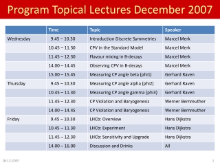
II.III. The RF system: synchronization with experiments (RF low level) Revolution frequency B1,B2 (40 MHz) Orbit frequency (11 kHz = fRF/h) CMS 5 LBDS 6 4 RF CCC Collim (p) Collim (beta) 3 7 PCR(CCC) SPS 8 2 TI8 ALICE LHCb 1 TI2 ATLAS GPS time Machine mode Beam type Beam energy Num. Injected bunches etc BST msg from LHC Timing System B.G. Taylor, “Timing distribution at the LHC”, 8th workshop on Electronics for LHC experiments, Comar 2002
II. The beam Contents: • Beam parameters • Injection mechanism • Injection from pre-accelerators • Injection into LHC • How the injection affects the beam parameters • Injection commissioning • The RF system • Functionality and beam parameters used to design it • RF components • RF synchronization: injection process and experiments • The vacuum chamber and the beam size • Acceleration
II.IV. Vacuum chamber & beam size • The beam vacuum requirements are very stringent, driven by the requested beam lifetime (100 hours) and background to the experiments • 1015 H2/m3 • 1013 H2/m3 in the interaction regions • Heat sources: • Synchrotron light radiated by the beam (0.2 Wm-2 per beam) • Energy loss by nuclear scattering (30 mWm-1 per beam) • Image currents (0.2 Wm-1 per beam) • Electron clouds Image current beam Beam pipe Synchrotron radiation from proton bunches in the LHC creates photoelectrons at the beam screen wall. These photoelectrons are pulled toward the positively charged proton bunch. When they hit the opposite wall, they generate secondary electrons which can in turn be accelerated by the next bunch. Depending on several assumptions about surface reflectivity, photoelectron and secondary electron yield, this mechanism can lead to the fast build-up of an electron cloud (the animation shows simulation results by O. Brüning for 10 subsequent bunch passages, during which the pictures become red) with potential implications for beam stability and heat load on the beam screen. By O. Brüning (AB/ABP CERN)
II.IV. Vacuum chamber & beam size In order to reduce the heat input to the cryogenic system the following design choices were made: • Beam screen determines the mechanical aperture • Cu layer • Gas density restriction Cold bore Cooling tubes (5-20 K) Dimensions: height ~ 2x17 mm width ~ 2x22 mm • The mechanical aperture, i.e. the beam screen: • Combined with a peak function in the arc of 180 m implies a maximum acceptable transverse beam emittance of n=3.75 µm. • Combined with the limit on the linear beam-beam tune shift limits the maximum bunch intensity to 1.15 x 10¹¹protons per bunch.
II. The beam Contents: • Beam parameters • Injection mechanism • Injection from pre-accelerators • Injection into LHC • How the injection affects the beam parameters • Injection commissioning • The RF system • Functionality and beam parameters used to design it • RF components • RF synchronization: injection process and experiments • The vacuum chamber and the beam size • Acceleration
II.V. Acceleration • Snap-back (topic for an advance school): • phenomena typical of SC magnets • happens during the first couple of seconds after acceleration starts • one needs to correct for it!!! Squeeze Lumioptimiz Acceleration ~20 min Snap-back Correct for them at the beginning of the ramp Persistent current decay effects!!!