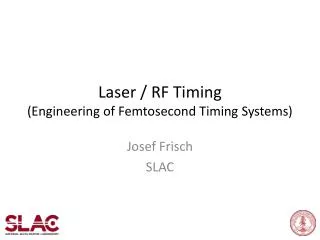
Lasers and RF-Timing
Lasers and RF-Timing. Franz X. Kaertner Department of Electrical Engineering and Computer Science and Research Laboratory of Electronics, Massachusetts Institute of Technology, Cambridge, USA. Outline. I. System Overview II. Timing Distribution III. RF-Synchronization

Lasers and RF-Timing
E N D
Presentation Transcript
Lasers and RF-Timing • Franz X. Kaertner • Department of Electrical Engineering and Computer Science and • Research Laboratory of Electronics, • Massachusetts Institute of Technology, Cambridge, USA
Outline I. System Overview II. Timing Distribution III. RF-Synchronization IV. Some Experimental Results V. Photo-Injector VI. Long Seed Pulse Generation VII. Conclusion
Facility concept Master oscillator Fiber link synchronization UV Hall X-ray Hall Seed laser Pump laser Seed laser Pump laser Undulators 100 nm Undulators 30 nm 1 nm Injector laser 10 nm 0.3 nm SC Linac 0.3 nm SC Linac 0.1 nm 1 GeV 2 GeV 4 GeV 10 nm Future upgrade to 0.1 nm at 8 GeV 3 nm 1 nm Undulators Seed laser Pump laser Nanometer Hall W.S. Graves, MIT Bates Laboratory
Timing Distribution Optical Master Oscillator Mode-locked Laser RF-Clock 100 MHz Timing Stabilized Fiber Links HHG-Seed Dt = 10 fs Probe Laser Dt = 10 fs Photo-Inj. Dt = 100 fs SC-Accel. 1.3 GHz Dt=200 fs Linearizer 3.9 GHz Dt=10 fs RF-Switch 0.65 GHz Dt=200 fs 10kHz 5ms Pulsed Klystron Undu- lator Gun Linac Dt: Required Timing Jitter in Each Section 10 fs ~ 3mm
Timing Stabilized Fiber Links (<1km) PZT Cross Correlator Fiber Fixed Length L ML - Laser Assuming no fiber length fluctuations faster than 2L/c.
Cooperation on Frequency Metrology and Timing Distribution Both at MIT and JILA-NIST: MURI-Projects funded by ONR Frequency Metrology and Femtosecond Technology for Optical Clocks MIT: E. P. Ippen (PI) Y. Fink F. Kaertner D. Kleppner L. Kolodziejski J. Shapiro F. Wong JILA-NIST: J. Ye (PI) S. Diddams L. Holberg ….. J. Ye, JOSA B 20, 1459 – 1469 (2003)
Experimental Results on Transmission of Optical Frequency Standards By active fiber induced phase noise cancelation
l 4 Sub-10 fs RF-Synchronization (Mike Perrott, MTL, MIT-Proprietary Information) Repetition Rate: fR PBS Phase Modulator RF: f = m fR Recovered from optical pulse train Loop Filter VCO
Experimental Results on Synchronization Synchronization of a 5fs Ti:Sapphire laser @ 800 nm and a 30 fs Cr:Forsterite laser @ 1300 nm with 0.3 fs timing jitter measured from 1mHz to 2.3 MHz.
1mm BaF2 5fs Ti:sapphire Laser f = 10o Laser crystal: 2mm Ti:Al2O3 OC 1 PUMP L = 20 cm OC 2 BaF2 - wedges Base Length = 30cm for 82 MHz Laser
Laser Spectra Ti:sapphire Cr:forsterite 5 fs 30 fs
Output (650-1450nm) Δt Cr:fo Ti:sa (1/496nm = 1/833nm+1/1225nm). SFG Rep.-Rate Control 3mm SFG Fused Silica Balanced Cross-Correlator 0V
Output (650-1450nm) Δt Δt Δt Cr:fo -GD/2 Ti:sa (1/496nm = 1/833nm+1/1225nm). SFG Rep.-Rate Control 3mm SFG GD 0V + - 0V Fused Silica Balanced Cross-Correlator + -
Measuring the residual timing jitter Jitter Output SFG Analysis (650-1450nm) Cr:fo -GD/2 Ti:sa (1/496nm = 1/833nm+1/1225nm). SFG Rep.-Rate Control 3mm SFG GD Fused Silica
Experimental result: Residual timing-jitter The residual out-of-loop timing-jitter measured from 10mHz to 2.3 MHz is 0.3 fs (a tenth of an optical cycle) Long Term Drift Free
1 Laser System & Synchronization Fiberlink + Synchronization Photo-Injector: 10-20 ps Pulses 1-10 mJ 1-10 kHz @ 266 nm (conv. NLO) High Harmonic Generation > 10 nJ Sub fs – 10 fs, 2ps 1-10 kHz @ 8,30,200 nm X00 m 10 fs Timing Jitter LINAC FEL E-beam
Directly Diode-pumped Photo-Injector To achieve a homogeneous e-beam bunch Temporal: Flat-top shaped Yb:fiber amplifier IPG-Photonics 20ps, 10mJ, 1-10 kHz @ 1064 nm 4th-Harmonic 20ps, 1mJ, 1-10 kHz @266 nm Acusto-Optic Programable Pulse Shaper (Dazzler, Fastlight) Yb:YAG, 1ps rep. Rate 100 MHz Pulse Selector
Long Pulse Seed Generation 2ps, 1mJ @ 200 (266) nm Yb: YAG CPA 2ps, 20mJ, 1-10 kHz @1064 nm 4th-Harmonic 2ps, 1mJ, 1-10 kHz @ 200 (266) nm Acusto-Optic Programable Pulse Shaper (Dazzler, Fastlight) Yb:YAG, 2ps rep. Rate 100 MHz Pulse Selector
Conclusions • Seeding needs 10 fs timing distribution over 300m distances (rel. precision 10-8). Can be accomplished by length stabilized fiber links. • Fiber noise eliminated by active feedback. • Scheme for phase stable RF-regeneration has been outlined • Less than 0.3 fs between independent lasers has been demonstrated, Optical Clock distribution. • Photo-Injection Laser: Mode-locked Yb:YAG laser and amplifier • Long wavelength seed: Mode-locked Yb:YAG laser and CPA