Download
1 / 64
680 likes | 1.08k Views
CHAPTER 17 CAPACITOR & DIELECTRICS (PST :3 hours) (PDT : 7 hours). 17.1 Capacitors 17.2 Capacitors in series and parallel 17.3 Charging and discharging of capacitors 17.4 Capacitors with dielectrics. 17.1 CAPACITORS . LEARNING OUTCOMES :.

E N D
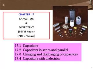
CHAPTER 17 CAPACITOR & DIELECTRICS (PST :3 hours) (PDT : 7 hours) 17.1 Capacitors 17.2 Capacitors in series and parallel 17.3 Charging and discharging of capacitors 17.4 Capacitors with dielectrics
17.1 CAPACITORS LEARNING OUTCOMES : At the end of this lesson, the students should be able to : • Define capacitance. • Use formulae, • Calculate the capacitance of parallel plate capacitor.
17.1 Capacitors • A capacitor , sometimes called a condenser, is a device that can store electric charge. • It is consists of two conducting plates separated by a small air gap or a thin insulator (called a dielectric such as mica, ceramics, paper or even oil). • The electrical symbol for a capacitor is or
Capacitance, C 17.1 Capacitors • The ability of a capacitor to store charge is measured by its capacitance. • Capacitance is defined as the ratio of the charge on either plate to the potential difference between them.
17.1 Capacitors • The unit of capacitance is the farad (F). • 1 faradis the capacitance of a capacitor if the charge on either of the plates is 1C when the potential difference across the capacitor is 1V. i.e. • By rearranging the equation from the definition of capacitance, we get where the capacitance of a capacitor, C is constant then (The charges stored, Q is directly proportional to the potential difference, V across the conducting plate.)
17.1 Capacitors • One farad (1F) is a very large unit. • Therefore in many applications the most convenient units of capacitance are microfarad and the picofarad where the unit conversion can be shown below :
Parallel-plate Capacitors • A parallel–plate capacitor consists of a pair of parallel plates of area A separated by a small distance d. • If a voltage is applied to a capacitor (connected to a battery), it quickly becomes charged. • One plate acquires a negative charge, the other an equal amount of positive charge and the full battery voltage appears across the plates of the capacitor (12 V).
17.1 Capacitors • The capacitance of a parallel-plate capacitor, C is proportional to the area of its plates and inversely proportional to the plate separation. Parallel-plate capacitor separated by a vacuum or Parallel-plate capacitor separated by a dielectric material 0: 8.85 x 10⁻¹² C2 N-1 m-2
Example 17.1 17.1 Capacitors • Calculate the capacitance of a capacitor whose plates are 20 cm x 3.0 cm and are separated by a 1.0-mm air gap. • What is the charge on each plate if the capacitor is connected to a 12-V battery? • What is the electric field between the plates? Answer :
Example 17.2 17.1 Capacitors An electric field of 2.80 x 10⁵ V m-1 is desired between two parallel plates each of area 21.0 cm2 and separated by 250 cm of air. Find the charge on each plate. (Given permittivity of free space, 0 = 8.85 x 10⁻¹² C2 N-1 m-2) Answer :
17.1 Capacitors Exercise 17.1 The plates of a parallel-plate capacitor are 8.0 mm apart and each has an area of 4.0 cm2. The plates are in vacuum. If the potential difference across the plates is 2.0 kV, determine a) the capacitance of the capacitor. b) the amount of charge on each plate. c) the electric field strength was produced.
17.2 Capacitors in series and parallel LEARNING OUTCOMES : At the end of this lesson, the students should be able to : • Deduce and use the effective capacitance of capacitors in series and parallel. • b) Derive and use equation of energy stored in a capacitor.
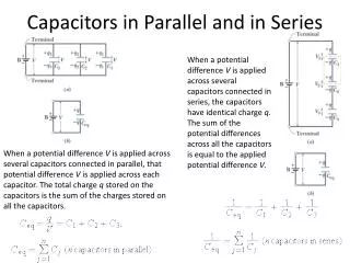
- Q +Q Ceq,V 17.2 (i) Capacitors connected in series 17.2 Capacitors in series and parallel V1 V2 V3 Q1 Q2 Q3 equivalent to • Figure above shows 3 capacitors connected in series to a battery of voltage, V. • When the circuit is completed, the electron from the battery (-Q) flows to one plate of C3 and this plate become negatively charge.
17.2 Capacitors in series and parallel • This negative charge induces a charge +Q on the other plate of C3 because electrons on one plate of C3 are repelled to the plate of C2. Hence this plate is charged –Q, which induces a charge +Q on the other plate of C2. • This in turn produces a charge –Q on one plate of C1 and a charge of +Q on the other plate of capacitor C1. • Hence the charges on all the three capacitors are the same, Q. • The potential difference across capacitor C1,C2 and C3are
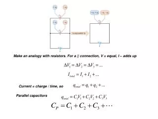
17.2 Capacitors in series and parallel • The total potential difference V is given by • If Ceq is the equivalent capacitance, then • Therefore the equivalent (effective) capacitance Ceq for n capacitors connected in series is given by capacitors connected in series
-Q +Q Ceq,V 17.2 (ii) Capacitors connected in parallel equivalent to • Figure above shows 3 capacitors connected in parallel to a battery of voltage V. • When three capacitors are connected in parallel to a battery, the capacitors are all charged until the potential differences across the capacitors are the same.
17.2 Capacitors in series and parallel • If not, the charge will flow from the capacitor of higher potential difference to the other capacitors until they all have the same potential difference, V. • The potential difference across each capacitor is the same as the supply voltage V. • Thus the total potential difference (V) on the equivalent capacitor is • The charge on each capacitor is
17.2 Capacitors in series and parallel • The total charge is and • Therefore the equivalent (effective) capacitance Ceq for n capacitors connected in parallel is given by capacitors connected in parallel
Example 17.3 17.2 Capacitors in series and parallel 50 V C1 = 1µF C2 = 2µF • In the circuit shown above, calculate the • charge on each capacitor • b) equivalent capacitance
Example 17.4 17.2 Capacitors in series and parallel • In the circuit shown below, calculate the • equivalent capacitance • b) charge on each capacitor c) the pd across each capacitor C1 = 1µF C2 = 2µF V1 V2 50 V
Example 17.5 • In the circuit shown below, calculate the • equivalent capacitance • charge on each capacitor • c) the pd across each capacitor C1 = 6.0µF C3 = 8.0µF V1 V2 =V3 12 V C1 = 6.0µF C23 = 12.0µF V1 V2 12 V
Example 17.6 17.2 Capacitors in series and parallel Find the equivalent capacitance between points a and b for the group of capacitors connected as shown in figure below. Take C1 = 5.00 F, C2 = 10.0 F C3 = 2.00 F.
Solution 17.6 17.2 Capacitors in series and parallel C1 = 5.00 F, C2 = 10.0 F and C3 = 2.00 F. Series a and Series b Series a Series b C12 C12 Parallel parallel C22
Solution 17.6 17.2 Capacitors in series and parallel C1 = 5.00 F, C2 = 10.0 F and C3 = 2.00 F. • a Parallel Parallel C3 C12 C12 Ca C22 • b
Solution 17.6 17.2 Capacitors in series and parallel • a Series series Ca Ceq C22 • b
1 F 1 F 1 F 1 F 1 F 1 F Example 17.7 17.2 Capacitors in series and parallel Determine the equivalent capacitance of the configuration shown in figure below. All the capacitors are identical and each has capacitance of 1 F.
1 F 1 F 1 F 1 F Ca 1 F 1 F Solution 17.7 17.2 Capacitors in series and parallel series series Ca series 1 F 1 F series 1 F Cb
Ceq Solution 17.7 17.2 Capacitors in series and parallel parallel Cb 1 F parallel
C1 a C2 d b C3 Exercise 17.2 17.2 Capacitors in series and parallel 1. In the circuit shown in figure above, C1= 2.00 F, C2 = 4.00 F and C3 = 9.00 F. The applied potential difference between points a and b is Vab = 61.5 V. Calculate a) the charge on each capacitor. b) the potential difference across each capacitor. c) the potential difference between points a and d.
17.2 Capacitors in series and parallel 2. Four capacitors are connected as shown in figure below. Calculate a) the equivalent capacitance between points a and b. b) the charge on each capacitor if Vab=15.0 V. 5.96 F, 89.5 C on 20 F, 63.2 C on 6 F, 26.3 C on 15 F and on 3 F.
17.2 Capacitors in series and parallel 3. A 3.00-µF and a 4.00-µF capacitor are connected in series and this combination is connected in parallel with a 2.00-µF capacitor. a) What is the net capacitance? b) If 26.0 V is applied across the whole network, calculate the voltage across each capacitor. 3.71-µF, 26.0 V, 14.9 V, 11.1 V
Energy stored in a capacitor, U 17.2 Capacitors in series and parallel • A charged capacitor stores electrical energy. • The energy stored in a capacitor will be equal to the work done to charge it. • A capacitor does not become charged instantly. It takes time. • Initially, when the capacitor is uncharged, it requires no workto move the first bit of charge over. • When some charge is on each plate, it requires work to add more charge of the same sign because of the electric repulsion. • The work needed to add a small amount of charge dq, when a potential difference V is across the plates is,
17.2 Capacitors in series and parallel • Since V=q/C at any moment , where C is the capacitance, the work needed to store a total charge Q is • Thus the energy stored in a capacitor is or or
Example 17.8 17.2 Capacitors in series and parallel A camera flash unit stores energy in a 150 µF capacitor at 200 V. How much energy can be stored?
Example 17.9 17.2 Capacitors in series and parallel • A 2 µF capacitor is charged to 200V using a battery. • Calculate the • charge delivered by the battery • energy supplied by the battery. • energy stored in the capacitor. Solution 17.9
Exercise 17.3 17.2 Capacitors in series and parallel Two capacitors, C1= 3.00 F and C2 = 6.00 F are connected in series and charged with a 4.00 V battery as shown in figure below. Calculate a) the total capacitance for the circuit above. b) the charge on each capacitor. c) the potential difference across each capacitor. d) the energy stored in each capacitor. e) the area of the each plate in capacitor C1 if the distance between two plates is 0.01 mm and the region between plates is vacuum. 2.00 µF 8.00 µC V1 = 2.67 V, V2 = 1.33 V U1 = 1.07 x 10 -5 J, U2 = 5.31 x 10⁻⁶ J 3.39 m 2
17.3 Charging and discharging of capacitors (1 hour) LEARNING OUTCOMES : At the end of this lesson, the students should be able to : • Define and use time constant, τ = RC. • Sketch and explain the characteristics of Q-t and I-t graph for charging and discharging of a capacitor. • Use formula for discharging and • for charging.
Charging a capacitor through a resistor 17.3 Charging and Discharging of Capacitor • Figure below shows a simple circuit for charging a capacitor. • When the switch S is closed, current Io immediately begins to flow through the circuit. • Electrons will flow out from the negative terminal of the battery, through the resistor R and accumulate on the plate B of the capacitor. • Then electrons will flow into the positive terminal of the battery, leaving a positive charge on the plate A.
17.3 Charging and Discharging of Capacitor • As charge accumulates on the capacitor, the potential difference across it increases and the current is reduced until eventually the maximum voltage across the capacitor equals the voltage supplied by the battery, Vo. • At this time, no further current flows (I = 0) through the resistor R and the charge Q on the capacitor thus increases gradually and reaches a maximum value Qo.
17.3 Charging and Discharging of Capacitor The charge on the capacitor increases exponentially with time The current through the resistor decreases exponentially with time Charge on charging capacitor : Current in resistor : where
Discharging a capacitor through a resistor • Figure below shows a simple circuit for discharging a capacitor. • When a capacitor is already charged to a voltage Voand it is allowed to discharge through the resistor R as shown in figure below. • When the switch S is closed, electrons from plate B begin to flow through the resistor R and neutralizes positive charges at plate A. C
17.3 Charging and Discharging of Capacitor • Initially, the potential difference (voltage) across the capacitor is maximum, V0 and then a maximum current I0 flows through the resistor R. • When part of the positive charges on plate A is neutralized by the electrons, the voltage across the capacitor is reduced. • The process continues until the current through the resistor is zero. • At this moment, all the charges at plate A is fully neutralized and the voltage across the capacitor becomes zero.
17.3 Charging and Discharging of Capacitor Charge on discharging capacitor : Current in resistor : The current through the resistor decreases exponentially with time. The charge on the capacitor decreases exponentially with time. The negative sign indicates that as the capacitor discharges, the current direction opposite its direction when the capacitor was being charged. For calculation of current in discharging process, ignore the negative sign in the formula.
Time constant, 17.3 Charging and Discharging of Capacitor • It is a measure of how quickly the capacitor charges or discharges. • Its formula, • Its unit is second (s). Charging process • The time constant is defined as the time required for the capacitor to reach 0.63 or 63% of its maximum charge (Qo). • The time constant is defined as the time required for the current to drop to 0.37 or 37% of its initial value(I0). when t=RC when t=RC
17.3 Charging and Discharging of Capacitor Discharging Process • The time constant is defined asthe time required for the charge on the capacitor/current in the resistor decrease to 0.37 or 37% of its initial value. when t=RC when t=RC
Example 17.10 17.3 Charging and Discharging of Capacitor Consider the circuit shown in figure below, where C1= 6.00 F, C2 = 3.00 F and V = 20.0 V. Capacitor C1 is first charged by the closing of switch S1. Switch S1 is then opened, and the charged capacitor is connected to the uncharged capacitor by the closing of S2. Calculate the initial charge acquired by C1 and the final charge on each capacitor.
Solution 17.10 17.3 Charging and Discharging of Capacitor After the switch S1 is closed. The capacitor C1 is fully charged and the charge has been placed on it is given by + + + + + - - - - - V C1 C1 C2 S1 S2 After the switch S2 is closed and S1 is opened. The capacitors C1 and C2 (uncharged) are connected in parallel and the equivalent capacitance is The total charge Q on the circuit is given by + + - - + -
Solution 17.10 17.3 Charging and Discharging of Capacitor The charge from capacitor C1 flows to the capacitor C2 until the potential difference V’ across each capacitor is the same (parallel) and given by + + + - - - C1 C2 S2 Therefore the final charge accumulates - on capacitor C1 : - on capacitor C2 :
Example 17.11 17.3 Charging and Discharging of Capacitor In the RC circuit shown in figure below, the battery has fully charged the capacitor. Then at t = 0 s the switch S is thrown from position a to b. The battery voltage is 20.0 V and the capacitance C = 1.02 F. The current I is observed to decrease to 0.50 of its initial value in 40 s. Determine a. the value of R. b. the time constant, b. the value of Q, the charge on the capacitor at t = 0. c. the value of Q at t = 60 s
Solution 17.11 17.3 Charging and Discharging of Capacitor