Download
1 / 24
240 likes | 909 Views
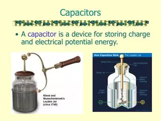
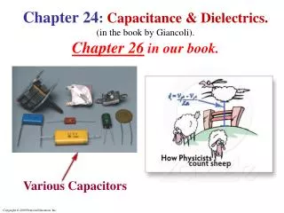
Learn about circuit diagrams, symbols, and how capacitors behave in series and parallel circuits. Explore formulas, charge, voltage calculations, and energy storage concepts.

E N D
Circuit Symbols • A circuit diagram is a simplified representation of an actual circuit. • Circuit symbols are used to represent the various elements. Lines are used to represent wires. • The battery’s positive terminal is indicated by the longer line.
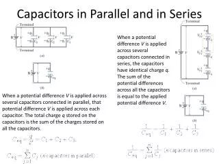
Capacitors in Parallel • When capacitors are first connected in a circuit, electrons are transferred from the left plate through the battery to the right plate, leaving the left plate positively charged & the right plate negatively charged.
Capacitors in Parallel • Capacitors in Parallel have • the same voltageVabacross • each one. The equivalent • capacitor Ceqis one that stores • the same total charge Qwhen • connected to the same battery. • That is, in the figure, Q = Q1 + Q2 + Q3 = C1V + C2V + C3V Also Q CeqVso the equivalent capacitance is:
Capacitors in Series • When a battery is connected to the circuit, electrons are transferred from the left plate of C1 to the right plate of C2through the battery. • As this negative charge accumulates on the right plate of C2, an equivalent amount of negative charge is removed from the left plate of C2, leaving it with an excess positive charge. • All of the right plates gain charges of –Q & all the left plates have charges of +Q.
Capacitors in Series • Capacitors in Series each have the same charge Q • their plates. That is in the figure, the equivalent capacitor • has the same charge across the total voltage drop: So, • V = V1 + V2 + V3 &Q = C1V1 = C2V2 = C3V3 CeqV This results in an equivalent capacitance: Note that The formula is for the inverse ofCeq& not forCeqitself!
Equivalent Capacitance, Example 26.3 See Figure! • The 1.0-μF and 3.0- μF capacitors are in parallel as are the 6.0- μF and 2.0-μF capacitors. • These parallel combinations are in series with the capacitors next to them. • The series combinations are in parallel and the final equivalent capacitance can be found.
Example: Equivalent Capacitance Calculate the capacitance of a single capacitor that will have the same effect as the combination shown. Let C1 = C2 = C3 C
Example: Charge & Voltage on Capacitors See figure. Calculate the charge on each capacitor & the voltage across each. LetC23 = 3.0 μF & the battery voltage V = 4.0 V.Note that the capacitance C23is the capacitance obtained from combining C2 & C3.
Example Capacitors Reconnected See figure. Two capacitors, C1 = 2.2 μF & C2 = 1.2 μF, are connected in parallel to a 24-V as in Fig. a. After they are charged, they are disconnected from the source & from each other. Shortly afterward, they are reconnected directly to each other, with plates of opposite sign connected together. Calculate the charge on each capacitor & the potential across each after equilibrium is established.
Example: Capacitors Reconnected Solution:C1 = 2.2 μF & C2 = 1.2 μF.
Example: Capacitors Reconnected Solution:C1 = 2.2 μF & C2 = 1.2 μF.
Example: Capacitors Reconnected Solution:C1 = 2.2 μF & C2 = 1.2 μF.
Energy in a Capacitor – Overview • Consider the circuit as a system. • Before the switch is closed, the energy is stored as chemical energy in the battery. • When the switch is closed, the energy is transformed from chemical potential energy to electric potential energy. • The electric potential energy is related to the separation • of the positive & negative charges on the plates. • So, a capacitor can be described as a device that • stores energy as well as charge.
Electric Energy Storage • A useful property of a capacitor is that, if it • is charged, it can store electric energy. The • energy stored by a charged capacitoris • equal tothe work done to charge it. • From the potential difference discussion, the • work to add an infinitesimal charge dq to a • capacitor which is at voltage V is: • dW = Vdq
Electric Energy Storage • dW = Vdq • So, if a capacitor C at voltage V is initially • uncharged, the work needed to bring charge Q to • the plates is • W = Vdq . (Limits are q = 0 & q = Q). • Note that, with charge q on the plates, V = (q/C). So • W = (1/C) qdq = (½)(Q2/C) • So, the energy stored in capacitor C with charge Q • at voltage V is:
Example: Energy stored in a capacitor • A camera flash unit stores energy in a 150-μF capacitor at 200 V. • Calculate • (a) The energy stored in the capacitor. • (b) The power output if nearly all this energy is • released in 1.0 ms.
Conceptual Example: Capacitor Plate Separation Increased • A parallel-plate capacitor is given a • charge Q on its plates & is then • disconnected from a battery. • The 2 plates are initially separated by • distance d. Suppose the plates are pulled • apart until the separation is 2d. How has the • energy stored in this capacitor changed?
Example: Moving Parallel • Capacitor Plates • The plates of a parallel-plate capacitor have area • A, separation x, & are connected to a battery at • voltage V. While connected to the battery, the • plates are pulled apart until they are separated by 3x. • Calculate • (a) The initial & final energies stored in the • capacitor. • (b) The work needed to pull the plates apart (constant speed). • (c) The energy exchanged with the battery.
Energy Density Parallel Plate Capacitor • Its sometimes useful to think of the energy • stored in a capacitor as being stored in the • electric field between the plates. • Consider a parallel plate capacitor with plate • separation d. E = Electric field between the • plates. We’ve seen that the capacitance is • We’ve also seen that the energy stored in a • capacitor C with charge Q at voltage V is:
Energy Stored in a Capacitor • For a parallel plate capacitor, the • voltage V between the plates is given • in terms of electric field E as: • V = Ed • Putting this into the expression for U • gives U = (½)ε0E2Ad • So, the energy density (energy per • unit volume) is • u = [U/(Ad)]oru = (½)ε0E2
Energy Stored in a Capacitor • The energy density (energy per unit volume) • stored in a parallel plate capacitor is • u = (½)ε0E2 • NOTE!!The sudden discharge of • electric energy can be • Harmful or even Fatal!! • So, please be careful!! • Capacitors can retain charge indefinitely even when • not connected to a voltage source! • So, PLEASE BE CAREFUL!!!!!!!!
This result for the energy density was obtained for a parallel • plate capacitor. However, the result is actually much more • general than that! It can be shown that the result • l • is valid anywhere in space where • there is an electric field. • So, in general, • The electric energy stored per unit volume in any region of space is proportional to the square of the electric field in that region.
Heart defibrillators use electric discharge to “jump-start” the heart, and can save lives.