Sequential Devices
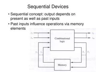
Sequential Devices. Sequential concept: output depends on present as well as past inputs Past inputs influence operations via memory elements. Sequential Devices. Input (x 1 ,…,x n ), output (z 1 ,…,z m ), present state (y 1 ,…,y r ) and next state (Y 1 ,…,Y r ) are

Sequential Devices
E N D
Presentation Transcript
Sequential Devices • Sequential concept: output depends on present as well as past inputs • Past inputs influence operations via memory elements
Sequential Devices • Input (x1,…,xn), output (z1,…,zm), present state (y1,…,yr) and next state (Y1,…,Yr) are where gi and hi are Boolean functions, or in vector form
Sequential Devices • Concept not limited to digital systems • Example: Elevator; has states: • Current position (floor) • Direction (up/down) • Next state depends on • Inputs (buttons pressed by passengers) • Current state (floor and direction) • State diagrams: graphical representation of sequential circuits • States: denoted by circles • Transitions: by arcs or arrows, labeled with inputs and outputs.
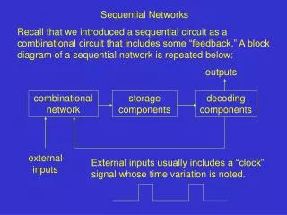
Sequential Devices • State tables: tabular representation of sequential circuits • Present state on the left, input on top • Next state / output is content of table cell
2 3 1 3 4 ? 2 Sequential Devices • Designing a good state representation is the most difficult part of designing sequential circuits • Case in point: elevator • Suppose state contains floor & direction • What happens on 2? 3,4 2,3,4 2 1 default 1,2,3
2 2 3 1 3 4 ? 3 2 Elevator • Suppose state diagram augmented by adding “hanging” states • Still problem: what happens in 2 when pressing “1”? Still have to remember you had “4”? 4 4 3,4 1 3 2 2 1 2 1,2,3 default 2 1,2
Elevator • A better approach: bit array 1…n, one per floor • “1” in the table indicates need to stop on that floor; Logic illustrated by program Begin /* the elevator main loop */ if (any bit is non-zero) if (current direction == nil) if (more bits are on above current floor than below) current direction = up else if (more bits are on below current floor than above) current direction = down else current direction = down /* might be random() */ endif /* end direction selection from previously nil */
Elevator begin /* at this point there is non-null direction; go! */ service next floor in current direction; set its bit = 0 until (no more bits are “1” in current direction) set current direction = nil /* done with direction, choose another */ else /* no bits were on */ set current direction = nil endif Again /* main loop forever */
Memory Devices • The memory unit is integral part of sequential machines • Memory is “bistable” – is output is either 0 or 1 • Has “excitation” inputs that bring it to the desired state • Commonly used – latches and flip-flops • Latches – typically “transparent”, respond immediately • Flip-flops have clocks, output changes only by clock
Memory Devices • Latch and flip-flop timing
Memory Devices • Simple feedback latches: set latch • Devices that stay permanently in one state are not very useful. Set and reset latches illustrate the concept, and serve as components of the set-reset latch
Memory Devices • Simple feedback latches: reset latch
Memory Devices • Simple feedback latches: set-reset latch
Set-reset latch • When S=R=0 reduces to a pair of cross-coupled inverters (hold state) • This is a stable configuration • When S=1 (R=0) then Q’ 0 • Bringing S back to 0 does not change the outputs; Q=1, Q’=0 (now S=R=0 again) • When R=1 (keeping S=0) then Q 0 • Bringing R back to 0 does not change the outputs; Q=0, Q’=1 • When S=R=1 then Q and Q’ are both 0 • not allowed **note: no oscillations, ckt stable** Q’ Q
SR latch • If S and R are asserted at the same time, output Q is not the complement of Q’ • What happens if S and R are asserted for some time, and then released simultaneously?
SR latch • This diagram assumes the NOR implementation of the SR latch
SR latch • SR latch propagation delays • This diagram assumes the NOR implementation of the SR latch
Gated SR latch • Uses extra control signal to inhibit state changes when the S and R signals are changing
Gated SR latch • Excitation table and state diagram of the gated SR latch
0 0 1 1 3 1 2 0 4 0 5 1 7 0 6 0 12 0 13 1 15 X 14 X 8 0 9 1 11 1 10 1 Gated SR latch • Logic function Q* = f(C,S,R,Q) • Q* = C’Q + SC + QR’ Set S = D; R = D’ R’ = D • Q* = C’Q + DC + QD = C’Q + CD (by consensus) • K-map of the gated SR latch SR CQ • C=0 Q* = Q+QR’ = Q • C=1 Q* = S+QR’ C’Q QR’ SC