Ladder Diagram Example
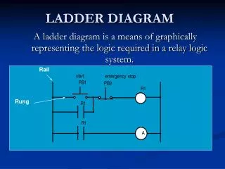
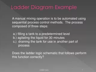
Ladder Diagram Example. A manual mixing operation is to be automated using sequential process control methods. The process composed of three steps : a.) filling a tank to a predetermined level b .) agitating the liquid for 30 minutes c .) draining the tank for use in another part of

Ladder Diagram Example
E N D
Presentation Transcript
Ladder Diagram Example A manual mixing operation is to be automated using sequential process control methods. The process composed of three steps: a.) filling a tank to a predetermined level b.) agitating the liquid for 30 minutes c.) draining the tank for use in another part of process Does the ladder logic schematic that follows perform this function correctly? et438b-7.pptx
Ladder Diagram Example Energized Press start open Solenoid A energized tank begins to fill Tank fills to limit open Timer goes To 30 minutes Timer energized Motor starts closed When tank drains flow switch resets. Timer resets open Mixer motor off Solenoid B on closed et438b-7.pptx
Combinational and Sequential Logic with Relays and Contacts Let contact state represent a logical value Implement AND gate et438b-7.pptx
Combinational and Sequential Logic with Relays and Contacts grd potential output A B = C Energized inputs Conditions A AND B must be present to energize output C Note: all contacts are considered instantaneous and not held unless modified With electromechanical relays fan-in and fan-out limited by number of contacts in relays et438b-7.pptx
More Logic Functions OR Function potential grd Energized A + B = C Boolean expression Either A OR B will cause coil C to be energized Contacts A, B represent conditions or states in the sequential process et438b-7.pptx
More Logic Functions NOT Function Boolean Expression B = A Contact of opposite state creates inversion et438b-7.pptx
Constructing Other Logic Functions Combine the AND function with the NOTfunction to get a NAND operation. 120 Vac grd Energized Any contact associated with coil D will change state like a NAND TTL gate. open De-energized Rung 1 implements the AND function Rung 2 implements the NOT function et438b-7.pptx
Multiple Input AND/NAND Energized Close AND NAND open A B C = E and A B C = E Can add a memory action to the above by including a feedback from the output coil to the inputs et438b-7.pptx
Memory Action AND/NAND Can add a memory action to the above by including a feedback from the output coil to the inputs Energized B and C are not sealed Close open et438b-7.pptx
All Inputs Latched AND/NAND Energized The output can not change unless the circuit is de-energized. Close open Contact E in rung 2 is a feedback from the output that makes circuit ignore state changes of A, B and C after the condition A B C is detected. et438b-7.pptx
Motor Control Example Three-wire control- used for manual and automatic motor starting. START OL3 OL1 STOP M1 seals-in the start PB. Motor stops when power lost M1 OL2 Control wiring 120 Vac GRD Thermal overloads actuate the control contacts OL1 to OL3 motor Motor Runs Power wiring et438b-7.pptx
Multiple Input OR/NOR Function OR A OR B OR C Energize E OR output NOR output Notice that Relay logic is similar to TTL. Can use Truth tables and Boolean expressions to do designs Outputs A+B+C = E A+B+C = E et438b-7.pptx
Ladder Logic Memory Elements Mechanically latched relay - maintains state even when power removed. Has two coils (operate, reset) Typical wiring Operate Latched Reset Latched Inputs A and B set the output contacts E and reset then respectively. This give toggle action that “remembers” the last input state even when power is removed Close Close Typical Applications Reversing Motor starters. Reclose Relay Cut-out et438b-7.pptx
Off-Return Memory Energize and re-energize circuit - Load 2 on No continuity in rungs 1-4 Continuity in rung 6 E On 1 Press A: continuity rung 2 Both loads on 2 E1 On 3 Press B: continuity rung 4 Both loads off 4 1 Load1 off 5 Close Load 2 off Open 6 2 Remember all contacts are drawn with the coils de-energized et438b-7.pptx
Timer Sub-Circuits Rung 1: when input A is energized timer TR-E starts TR-E On Load off Open 1 Load on Close 2 Load off Open 3 Schematic indicates that this is a on-delay timer. After defined interval TR-E in rung 2 opens and TR-E in rung 3 closes Load 1 is deactivated after time delay Load 2 is activated after time delay Load 3 is instantaneously deactivated by TR-E et438b-7.pptx
Form “C” Contact Loads are toggled between a common point Typical “Form C” contacts include both a NO and NC contact arrangement. Used in some sensors for more flexibility Contact A creates a remote control toggle switch et438b-7.pptx
Designing Sequential Control Systems et438b-7.pptx
Review of Logic Gates and Boolean Algebra False =0 True =1 Boolean Variables Boolean Operators EOR=XOR Alternate Implementation et438b-7.pptx
Review of Logic Gates and Boolean Algebra Axioms of Boolean Algebra Idempotent Associative Distributive Identity Complement DeMorgan’s Theorem Absorption Order of Operations NOT 2. AND 3. OR et438b-7.pptx
Review of Logic Gates and Boolean Algebra Example: Simplify the following expression using the axioms of Boolean Algebra. Add Parentheses Apply DeMorgans’s Theorem to first term Apply DeMorgan’s Here Expand Expressions Collect common terms and factor et438b-7.pptx
Review of Logic Gates and Boolean Algebra Example Continued Use Complement Axiom Use Identity Axiom Simplified Expression et438b-7.pptx
Logic Design 1.) Obtain description of process 2.) Define control action 3.) Define Inputs and Outputs 4.) Develop Truth Table or Boolean Equation of Process Process control description A heating oven with two bays can heat one ingot in each bay. When the heater is on it provides enough heat for two ingots. If only one ingot is present, the oven may overheat so a fan is used to cool the oven when it exceeds a set temperature. Control Action When only one ingot is in the oven and the temperature exceeds the setpoint, turn on the fan et438b-7.pptx
Logic Design Define I/O variables Inputs: B1 = bay1 ingot present B2 = bay2 ingot present T = temperature sensor Output: F= fan start Create Truth Table If there is no over temperature don’t start the fan Over temperature in empty oven: safety fan start Start fan in lightly load ovens with over temp. Over temperature in full oven: safety fan start et438b-7.pptx
Logic Design Select elements from truth table in SOP (sum-of-products) form then simplify. Requires only Temp control Ignore unloaded and full load cases and try again et438b-7.pptx
Logic Design Revised Truth Table Ladder Logic Representation et438b-7.pptx
Simplified Forms of Functions Avoid multiple complemented variables in ladder logic (No NAND, NOR) NOR NAND NAND/NOR can not be implemented effectively using software. (Programmable Logic Controllers) et438b-7.pptx
State-Based Designs Definitions State- current operational mode of system Examples: On/Off, Idle, Tank filling, dispensing product. Conditions (inputs) - inputs required for leaving the current state and moving to another state Examples: Coins inserted, button pressed, OL activated Actions(outputs) - actions performed by system when the transition from one state to another take place Examples: Start motor, turn on light, sound alarm. et438b-7.pptx
State-Based Designs When a set of inputs (conditions) become valid for leaving a state, the system is directed to the destination state State exit input conditions To other states CurrentState NextState State outputs State entry input conditions et438b-7.pptx
State Transition Diagrams State transition diagrams allow designers to examine the interaction between desired conditions and find their logical relationships and sequence. Use in digital computer design Else Else B State 2 State 1 A State 3 Else If C true go to State 1 Else State 3 C If Condition A true go to State 2 Else stay in State 1 If B true go to State 3 Else State 2 et438b-7.pptx
State Equations Informal: State X =(State X +Arrival from another state) and has not left for another state State n Re-seti,= logical condition to reset state variable i and leave State m setn resetm . . . . State i State j State k seti reseti . . . . . . set2 reset2 State 2 State 2 set1 reset1 State 1 Seti=logical condition to set state variable i and enter state State 1 et438b-7.pptx
State Equations Set Conditions Functions of state and inputs Formal Definition: Reset Conditions Functions of state and inputs Where: statei = a variable that reflects state i is on statei+1 = next value of state variable outi = desired outputs of state i hi( ) = output function of state variables n = number of transitions into state i m = number of transitions out of state i N = total number of system states seti= logical condition to set state variable i reseti = logical condition to reset state variable i et438b-7.pptx
Example Write the state equation for a motor starting control described in the state diagram below with the following input and outputs S1 (Start) X1=1 I0=pressed stop button (PB1) I1= pressed start button (PB2) I2 = motor overload condition (OL) O1 = start motor (M) S0 (Stop) X1=0 Only 1 state variable required for two conditions X1=0 or X1=1 Output equation et438b-7.pptx
Example Boolean Equation to ladder logic diagram Substitute variable names Construct Ladder et438b-7.pptx
Design Example: Reciprocating Motion Process A work piece must travel back and forth on a conveyor. The location of the work piece is determined by two limit switches. When the location is detected control signal are sent to a reversing motor contactor. The machine is started and stopped from a local set of push button switches. Develop a ladder logic diagram to implement this control. et438b-7.pptx
Design Example: Reciprocating Motion Process Determine the inputs, outputs and states of system Inputs: I0: press start I1: press stop I2: Table at reverse limit (1LS) I3: Table at forward limit (2LS) Outputs: O0: Start motor forward (2CR) O1: Start motor reverse (3CR) States: S0: off S1: on-forward, S2: on reverse, I0 I1 I2 I3 O0 O1 et438b-7.pptx
Design Example: Reciprocating Motion Process Assume machine starts at reverse limit. (1LS changes state) S1 (on-forward) S2 (on-reverse) S0 (Stop) O0 start forward action I0: press start I1: press stop I2: Table at reverse limit (1LS) I3: Table at forward limit (2LS) O1 start reverse action et438b-7.pptx
Design Example: Reciprocating Motion Process Define set and reset conditions Define 2 state variables X1 and X2 S1 (on-forward) S2 (on-reverse) S0 (Stop) X1=1 X2=0 O0 O1 Outputs X1=0 X2=1 et438b-7.pptx
Design Example: Reciprocating Motion Process Convert state equations into ladder diagram 2CR = O0 3CR =O1 I0=start I1=stop I2=1LS I3=2LS et438b-7.pptx
States With Prioritization Systems with multiple entries and exits from a state require blocking of Alternatives. S2 S0 D B Two Choices IF A THEN block C IF C THEN block A S1 C A given priority to C A A or C can occur independently to exit S1. Must give one transition priority over other. Block setting of conflicting state C over A et438b-7.pptx
Prioritization Example S0 S1 Inputs Outputs A P B Q C R D E F FS S2 Write state equations for this system. Give state S2 priority over S0 Output Map et438b-7.pptx
Prioritization Example Write state equations using transitions S0 blocked if S2 is active Simplify using DeMorgam’s Theorem Output Equations Output Map et438b-7.pptx