Linac4 Ion Source commissioning: Vacuum Aspects
180 likes | 401 Views
Linac4 Ion Source commissioning: Vacuum Aspects. C.Pasquino , N.Thaus , J.Hansen , P.Chiggiato. Outline. Vacuum aspects and lay-out; Vacuum simulation benchmark; Beam transmission measurements; NEG pump activation procedure and monitoring; Vacuum sealing: problems faced and solutions;

Linac4 Ion Source commissioning: Vacuum Aspects
E N D
Presentation Transcript
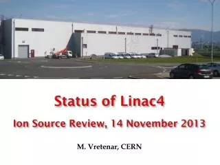
Linac4 Ion Source commissioning: Vacuum Aspects C.Pasquino, N.Thaus, J.Hansen, P.Chiggiato Linac4 Ion Source Review - 14th November 2013
Outline • Vacuum aspects and lay-out; • Vacuum simulation benchmark; • Beam transmission measurements; • NEG pump activation procedure and monitoring; • Vacuum sealing: problems faced and solutions; • Main achievements; • Maintenance & resources. Linac4 Ion Source Review - 14th November 2013
Vacuum lay-out SIP RFQ: LEBT: SIP H2 flux at 1*10-3 mbar l/s NEG Continuous injection at 1*10-5 mbar TMP SOURCE: NEG TMP Pulsed injection at 5*10-3 mbar l /pulse TMP RFQ TMP LEBT This value measured during the commissioning of the source by approximately5*10-2 mbar l /pulse. Source • The two major pressure constraints are: • The peak pressure during RF pulsing in the RFQ (5*10-7 mbar); • Operation of the NEG pumps; Courtesy of D. Steyaert Linac4 Ion Source Review - 14th November 2013
Vacuum lay-out SIP RFQ: LEBT: SIP H2 flux at 1*10-3 mbar l/s NEG Continuous injection at 1*10-5 mbar TMP SOURCE: NEG TMP Pulsed injection at 5*10-3 mbar l /pulse TMP RFQ TMP LEBT This value measured during the commissioning of the source by approximately5*10-2 mbar l /pulse. Source • The two major pressure constraints are: • The peak pressure during RF pulsing in the RFQ (5*10-7 mbar); • Operation of the NEG pumps; Courtesy of D. Steyaert Linac4 Ion Source Review - 14th November 2013
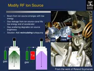
Vacuum Simulation benchmark: plasma chamber Hot cathode ionization gauge N2 H2 N2 and H2 injections for different pulse lengths. H2 N2 Gas injection and fast pressure-rise measurements for the Linac4 H−source E. Mahner, P. Chiggiato, J. Lettry, S. Mattei, M. O'Neil, H. Neupert, C. Pasquino, C. Schmitzer Linac4 Ion Source Review - 14th November 2013
Vacuum Simulation benchmark: LEBT Penning Gauge monitoring: pulsed gas injection from the source + gas density regulation on the LEBT. During this measurement the gas injection in the LEBT was about 3*10-6 mbar in H2 equivalent. LEBT: measurement H2 LEBT: simulation We are working outside of the vacuum limits set in the baseline design: Plebt max = 4.5*10-5 mbar> 1*10-5mbar, leading to a maximum P in the RFQ of 1*10-6 mbar (9.6*10-7 mbar average measure) . H2 Linac4 Ion Source Review - 14th November 2013
Operation of the IS at 2 Hz? These profiles have been simulated considering the H2 injection from the source and the gas density regulation on the LEBT. If we increase at 2 Hz the operation of the source there will be less pressure recovery time between two subsequent pulses: the base pressure of the LEBT with no injection would be in the 3*10-6 mbar, while now is in the high 10-7 mbar range. The actual intensity pulse at 2Hz is not compatible with the vacuum layout of the RFQ as it is designed. Linac4 Ion Source Review - 14th November 2013
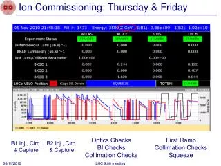
Monitoring the pressure in the RFQ • The pressure is monitored via two cold cathode gauges, positioned on the first and third tank. • The RF is interlocked by two ion pumps located at each end of the RFQ and the cold cathode gauge positioned on the first tank: the valves are interlocked at 1*10-6 mbar, the RF is interlocked at 5*10-7 mbar. • We do not have any fast acquisition on these penning gauges: the data are logged with a time interval which is longer than 2s, which is sufficient for monitoring the vacuum pressure in the RFQ. • In case we need the fast logging, we can access the data the L4 IS team have. • On the RFQ a dedicated residual gas analyzer is mounted: it has been used during the commissioning phase of the source and the RFQ in order to monitor the partial pressures of several gaseous species. Their evolution was monitored during the RF commissioning as well as during the NEG pump activation. Linac4 Ion Source Review - 14th November 2013
RGA signals during beam transmission in the RFQ: effect of beam losses. Source and LEBT gas load The residual gas analyzer was monitoring the ionic current of several gaseous species during the transmission measurement. H2 Injection ( 5*10-7 – 2*10-6 mbar), H2 leading gas; Sparking activities of the RFQ (beam lost): CO, CO2, CH4, C4H7, C4H9. Linac4 Ion Source Review - 14th November 2013
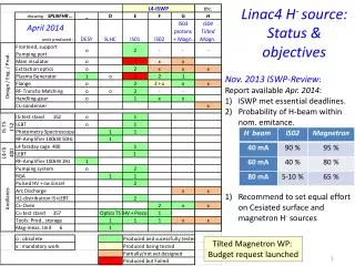
NEG pumps activation: monitoring & regeneration By isolating the turbo molecular pumps and switching on and off the sputter ion pumps it was possible to monitor the pumping speed of the NEG pumps. H2 Leak of 1*10-8 mbar l/s on a feedthrough!! Considering the actual pulsed and the LEBT continuous H2 gas injection, the regeneration of the 4 NEG pumps has to take place every 27 weeks of operation. At 2 Hz or at a higher gas injection rate this value will decrease even more! We need to install a new version of the NEG pumps from SAES, specifically conceived for this application, to achieve the baseline design (1 year of operation with no regeneration). The regeneration time for the NEG pumps is 24 h during technical stops! Linac4 Ion Source Review - 14th November 2013
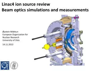
Source Assembly and leak tightness • Several type of sealing are used: • O-ring (elastomeric sealing) on the plasma generator ( ) • Single and Double diamond aluminum sealing / aluminum helicoflex sealing on the plasma extraction region • ( ) • - S S D c Conflat gaskets ( ) • Both Helicoflex and diamond seals are suited for the source: • With the actual design both types have been used; • Main leak tightness problem on the double diamond seals ( e.g non conformity of the seals); • Main drawback: if a double diamond seal is leaky, the whole assembly has to be dismounted; • The new design will only have single diamond/ helicoflex seals (widely used at CERN). The source is equipped with metal seals except for the plasma generator. Linac4 Ion Source Review - 14th November 2013
Source Assembly and leak tightness Linac4 Ion Source Review - 14th November 2013
Maintenance and resources (1): Ion sources • Considering the existing sources and 1 or 2 prototypes per year, we will have to take care of the maintenance of up to 6 ion sources, up to the end of the R&D; • Cesiated source: • Cs is not expected to be spurted inside the area of the vacuum pumps, but time is needed to measure and evaluate eventual problems (learning phase). • For sure the dismantling of the cesiated source will require more time due to inspection of the inner surfaces of each component. • The maintenance will require: • Change of the source every 3 months. • TE-VSC will be required for the preparation, testing, assembly, leak detection, disassembly of all new prototypes and old sources. Linac4 Ion Source Review - 14th November 2013
Maintenance and resources (2): Man power and Material costs The expected total work load will be 12 weeks per year. In addition, 2 weeks of standard maintenance of the vacuum pumps has to be foreseen (0.3 FTE/y, 1.2FTE for 2014-2017). The 1.2 FTE is not in the Work Package and extra man power (industrial support) will be required to fulfill this task, equal to 40KCHF/y or to a total of 160 KCHF. The total cost to run the two source installations in building 400 and 152 is 25KCHF per year. This cost is not taking into account the maintenance and modification of the installations in building 357. All pumping units installed on the source will be 5 years or more before Linac 4 will be connected to the PS-Complex in 2018 and a full replacement of all pumps shall be integrated in the maintenance cost for 2018. Man Power + Material ≈ 485 kCHF Linac4 Ion Source Review - 14th November 2013
Maintenance and resources (3): Additional tasks Additional requests, participation in: • Fast Gauge Test Stand: • Identify suitable fast injection valves, already existing in the industry (if possible); • Maintenance and intervention on the test bench in building 357; • Simulation benchmark on the time dependent pressure profiles with the different type of valves; • RGA in L4 tunnel: • The RGA might be monitored locally in the control room with a dedicated PC, following signals of individual masses (1-100 amu); • No software automatically analyzing these data will be implemented; • This will be important for the long term optimization of the source; • RGA has been purchased, but the installation costs of the RGA will have to be covered by the project (PC, Cabling, Pumping system). • Magnetron source; • It is not expected any modification in the vacuum system except on the source gas injection that is not under the TE-VSC responsibility; • New time dependent simulations are required in order to fully evaluate the impact of the new injection on the vacuum system; We regret, we do not have the necessary manpower to take part in these activities, unless a GET fellow is paid by the project (210 kCHFin two years). Linac4 Ion Source Review - 14th November 2013
Achievements • Simulation of time dependent pressure profiles, for the several design scenarios and for the actual design; • Benchmark of the simulations with fast pressure measurements: good correlation between the two; • Study of high efficiency hydrogen pumping materials (not compatible with Linac4 environment); • PVSS implementation for pressure monitoring for L4 and 3MeV test stand; • Assembly and leak testing of the different type of sources; • LEBT gas density regulation: injection line and control; • Contribution in the design of the sources. Linac4 Ion Source Review - 14th November 2013
Conclusions/summary • The Linac4 Source Work Package for vacuum is completed: all the tasks listed in the review of November 2011 are fulfilled. • In order to cope with the maintenance needed for the sources, 1.2 FTE for 2014-2017 are needed: these tasks can be covered by extra resources (industrial support), leading to a total cost of 160 kCHF. • Regarding the hardware maintenance and purchase of new material, the total cost would be around 325 kCHF: 165 kCHF in 2014-2017; 160 by 2018 for the final installation before operation. • If additional tasks are needed (Fast gauges test stand; local monitoring of L4 RGA and design and development of the magnetron source;) no extra resources can be delivered by TE-VSC. A GET fellow paid by the project (210 kCHF per 2 years of contract) could fulfill these activities. Linac4 Ion Source Review - 14th November 2013