Download

1 / 25
260 likes | 400 Views
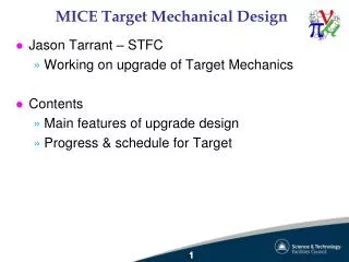
MICE- AFC Unit Mechanical Design of the Cold Mass Support System. Oxford University. Rohan Senanayake. Complete Assembly. General Arrangement of the cold mass support system. An Overview of AFC Unit. Cold Mass Bobbin G10 Insulation Focusing Coils

E N D
MICE- AFC UnitMechanical Design of theCold Mass Support System Oxford University Rohan Senanayake
An Overview of AFC Unit • Cold Mass • Bobbin • G10 Insulation • Focusing Coils • Cover Plate/Mounting brackets for Cold Mass • Copper Shield • End Plates and Cylindrical Core • Cold Mass Support System • Warm Vessel
Bobbin G10Insulation Focusing Coil Bobbin with G10 Insulation and Focusing Coils Coil Cover Plate with Cold Mass Support Brackets Cold Mass
Cold Mass Support System • 4 sets of Links anchored to the Cold Mass and Outer Casing to carry an Axial load on Cold Mass of 200 KN. Each link is pre-tensioned to 50 KN when cold. • Each pair of links is skewed relative to each other to provide torsional stiffness • Each Link is made of 2 Glass fiber Epoxy (E-Glass) links and one stainless steel link cooled to 500K. All the links and the cold mass support system are linked through stainless steel pins. • Anchor point on the outer casing includes a mechanism to pre-tension the links and help to align the cold mass accurately
450 Plane Vertical Plane Arrangement of the links to provide Torsional Stiffness
Components of the Cold Mass Support System • E-Glass Straps • Stainless Steel Block • Stainless Steel Shear Pins • Integrated Tensioning Device/ Anchor on warm vessel • End Cap • Mounting Bracket for Cold Mass Support
Stainless Steel Block E Glass Strap
Components of the Integrated Tensioning Device/ Anchor on warm vessel The device also prevents twisting of the link during the tensioning operation.
Integrated Tensioning Device/ Anchor on warm vessel End Cap welded to form a vacuum tight joint.
Pre -Tension Control T = 0.2 Fi dp T – Torque in N-m Fi – Tension in support link KN dp – pitch diameter of thread mm Example
Position Control of Cold Mass One turn of the nut moves the screw (cold mass) through one pitch. Pitch of screw = 2 mm Therefore one turn of the nut moves the corresponding mounting point of the cold mass through 2 mm A table showing the relationships between angular and radial positions of the cold mass centre line and rotation of the adjustment nuts will be compiled. This can be used during the assembly/ setup
Summary statement The design on the Cold Mass support system is adequate to take on the imbalance magnet force while allowing independent adjustment of the position of cold mass Further work Dip in the vessel shell under tension load: Manual calculations indicate a deflection of 0.5mm. A FE analysis will be done and the anchor points will be strengthened locally if necessary Shrinkage during vacuum: Would this shrinkage reduces the pre-tension load? Table of the adjustment of the individual cold mass support link to the positioning / alignment of the magnet. These will be ready by the next collaboration meeting in October.