Download
1 / 53
530 likes | 619 Views
EC312 Lesson 1 : Cyberphysical : Computer Architecture/ Digital Data. Why are You Here in EE’s Cyber 2?. 1 . In his book Worm, The First Digital World War (Atlantic Monthly Press, 2011), author Mark Bowden opines:

E N D
EC312 Lesson 1:Cyberphysical:Computer Architecture/Digital Data
Why are You Here in EE’s Cyber 2? • 1. In his book Worm, The First Digital World War (Atlantic Monthly Press, 2011), author Mark Bowden opines: • Most people, even well-educated people with formidable language skills, folks with more than a passing knowledge of word-processing software and spreadsheets and dynamic graphical displays, people who spend hours every day with their fingertips on keyboards, whose livelihoods and even leisure-time preferences increasingly depend on fluency with a variety of software remain utterly clueless about how any of it works. The innards of mainframes and operating systems and networks are considered not just unfathomable but somehow unknowable, or even not worth knowing, in the way that many people are content to regard electricity as voodoo.
What happens when such people, albeit well-intended and bright, use DOD computer networks? • The answer: Such individuals open their computers and networks to malicious attack. In November 2008, a Pentagon employee arrived for work, parked his car, and noticed thumb drives on the pavement. Not wanting to see resources go to waste, he collected the thumb drives and proceeded to plug one into his office computer, thereby spreading a damaging virus throughout the secure classified network he had access to use. Millions of man-hours expended on making a network secure can be wasted by one careless user in the face of a devious foe. Dr. Paul Vixie, an Internet pioneer and former Chairman of the American Registry for Internet Numbers (ARIN) is famously quoted as saying: • These security problems have been here so long that the only way I’ve been able to function at all is by learning to ignore them. Or else I would be in a constant state of panic, unable to think or act constructively. We have been one command away from catastrophe for a long time now. • And of course adversaries are continuously attempting to breech the security of DOD computers and networks. In the CNO’s view, the Navy’s information capabilities must evolve from a 20th-century supporting function to a main battery of 21st-century seapower. In this new vision for an information-centric Navy, information will be treated as a weapon across the full range of military operations, on the sea, under the sea, on land, and in the air. The U.S. Navy, in the CNO’s words, “stands on the cusp of a revolution comparable to the introduction of nuclear power into the Fleet.”
SI110 and EC310/312 • USNA has always adapted its academic program to satisfy the relevant needs of the Navy and Marine Corps. The curriculum is continually adjusted in order to ensure that midshipmen are prepared academically for the current and emerging challenges they will face as officers. Against the emerging cyber threat, USNA has deemed it urgent to tailor its program to meet the specific needs of users in cyberspace. Thus, USNA endeavors to graduate officers with a common understanding of the concepts, principles and applications of cyber security in order to ensure the protection and the availability of the Navy’s information systems and networks. This understanding is provided through a two course sequence: SI110 Introduction to Cyber Security and EC310/312 Applications ofCyber Engineering. • The trained and aware user is the first and most vital line of defense. Any officer, in any warfare specialty, may find himself the critical link in his organization’s network security posture. Thus, the goal is to infuse a baseline scientific and academic cyber-security education in all midshipmen, in order to address the need for cyber-capable unrestricted line officers that understand the threats and vulnerabilities at a basic technical level.
Review Topics for the Host section • Computer Hardware • RAM • Hard Drive • CPU • Peripherals • CPU Function • Fetch-Decode-Execute Cycle
Further review topics from SI110 and ES201 • Number Bases • Decimal -> Base 10 • Binary -> Base 2 • Hexadecimal -> Base 16 • Operations • Conversion • Arithmetic • Counting • Coding • Logic
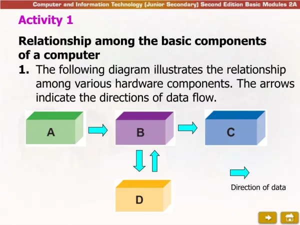
Computer Hardware • Random Access Memory (RAM) • Short Term Memory • Hard Drive • Long Term Memory • Central Processing Unit (CPU) • Thinking/Solving/Deciding • Peripherals • Interacting with surroundings
Computer systems consist of hardware and software: • Hardware: the actual electrical and mechanical components; the physical machines that make up a computer system. • Software: instructions that tell a computer how to do a specific job.
Digital Data Topics • Number Bases • Decimal -> Base 10 • Binary -> Base 2 • Hexadecimal -> Base 16 • Operations • Conversion • Arithmetic • Counting • Coding • Logic
Positional number system1 • The number system we learned in elementary school is an example of a positional number system. • Numbers are composed of a weighted string of digits and the weightings are determined by the digit’s position. weighting of each digit’s position 1 Much of this discussion comes from John F. Wakerly’s Digital Design: Principles and Practices, 2nd ed.
Decimal numbers • Each digit can take one of ten values. • The weighting of each digit’s position is a power of 10. • Hence, decimal numbers are called “base 10” or “radix 10.” 0, 1, 2, 3, 4, 5, 6, 7, 8, 9 weighting of each digit’s position
Digital signal • Digital signals are limited to a finite number of discrete amplitudes. • In digital computers, the most basic unit storage can take one of only two values, 1 or 0.
Binary numbers • Each binary digit (or bit) can take on one of two values. • The weighting of each bit position in a binary number is a power of 2. • Binary numbers are called “base 2” or “radix 2.” • Binary numbers are denoted by the subscript 2. 0 or 1
Binary numbers • The leftmost bit is called the most significant bit (MSB) because it has the largest weighting. • The rightmost bit is called the least significant bit (LSB) because it has the smallest weighting. 10110111 most significant bit (MSB) least significant bit (LSB)
Binary to decimal conversion • We can convert from a binary number to a decimal as previously indicated. • It is helpful to be familiar with powers of 2.
Example Problem Bin to Dec Convert the binary number 1101102 into decimal.
Example Problem Bin to Dec Convert the binary number 1000002 into decimal. sum the weight values corresponding to the 1s in the binary number
Decimal to binary conversion • To convert from decimal numbers to binary: • Find the highest power of 2 less than or equal to the decimal number. • Now subtract this power of 2 from the decimal number. • If the remainder is 0 you are done, if not, repeat the process. Convert 7810 into binary. first remainder becomes the right-most digit 1 0 0 1 1 1 02 64 32 16 8 4 2 1 stop when number equals zero
Example Problem Dec to Bin Convert 18210 into binary.
Example Problem Dec to Bin Convert 18210 into binary. # Bits 182 -128 = 54 1 0 54 - 32 = 22 1 22 - 16 = 6 1 0 6 - 4 = 2 1 2 - 2 = 0 1 0 1 0 1 1 0 1 1 0
Counting in Binary Using binary addition, count in binary from 0 to 8. 8 4 2 1 0 0 0 0 0 0 0 0 1 1 0 0 1 0 2 0 0 1 1 3 0 1 0 0 4 0 1 0 1 5 0 1 1 0 6 0 1 1 1 7 1 0 0 0 8 alternating eight 0s and eight 1s
Hexadecimal (base 16) • While natural for machines, binary numbers are inconvenient because of the number of bits required to represent large numbers. • In hexadecimal, each digit can take one of 16 values.
Hexadecimal conversion • Converting between hexadecimal and binary is simple because each hex digit is described by exactly 4 bits. 1001 1111 0010 10102binary 9 F 2 A hex
Example Problem Hex to Bin Convert 13F16 = 0x 13F to binary.
Example Problem Hex to Dec Convert 3CB16 = 0x 3CB to decimal.
American Standard Code for Information Interchangecode- ASCII
ASCII codes characters • Each ASCII symbol is shown with both its hexadecimal representation and its base-10 representation. Suppose we wanted to know how the symbol for the question mark is stored internally within the computer. Scanning the table for the question mark, we locate it at the bottom of the second column, and we note that its hexadecimal value is 3F. Converting this hexadecimal value to binary, we conclude that the question mark is stored as 00111111. • Example • How is the letter t stored in memory? • Solution:
Digital Logic • Digital data can be added and subtracted ( 2’s complemented) as binary operations. • [0 + 1= 1] (addition) • Digital data can also have logical operations, so make sure you know the difference in the expressions using variables. • [1 + 1 = 1] ( logical OR) • So we need to know the context for the operation, so let’s review a little bit of digital logic.
+5 V +5 V = buckled 0 V = not buckled Digital example: seatbelt switch • Consider a seatbelt warning. • This digital signal (A) consists of one of two possible logic values: • Seatbelt not buckled: A = 0 (off, low, FALSE) • Seatbelt buckled: A = 1 (on, high, or TRUE) m P R O C E S S O R A
+5 V ignition switch A C B +5 V brake pedal switch Digital example: ignition switch • Now consider starting a car. • To power the starter (signal C), two conditions must be met: • Ignition switch (signal A = 1) must be closed, AND • Brake pedal must be depressed (signal B = 1) m P R O C E S S O R
(signal B) brake pedal switch (signal A) ignition switch Digital example: ignition switch • We could represent this decision by listing all the possible input values and resulting output values. • This listing is called a truth table. Output Inputs output (signal C) brake pedal switch
A B AND function • The output C is true (i.e., logic 1) when bothA and B are true. • This logic function is called the AND operation and is expressed A·B. Inputs Output Inputs Output inputs output inputs output C = A·B Symbol for two-input AND gate
Logic gates • A logic gate is a circuit that takes several logic inputs and produces a logic-variable output. • The gates that we will cover are memoryless • In other words, their output at an instant in time depends only on the inputs at that instant. Output Inputs inputs output A C = A·B B Symbol for two-input AND gate
A Logic inverter • The inverter performs a logical NOT operation. • The output is the inverse of the input. • The symbol Āis read as “not A” or “A inverse.” • The bubble placed at the output of the inverter symbol is used to indicate inversion. bubble Ā Symbol for an inverter
A B OR gate • Output C is true (logic 1) if eitherA or B is true. • Note that the output is also true if both inputs are true • This logic function is called the OR operation and is expressed A+B. Inputs Inputs Output Output inputs output inputs output C = A+B Symbol for two-input OR gate
A B D C Logic circuits • These basic gates can be combined to implement more complex logic expressions.