IV–2 Inductance
IV–2 Inductance. Main Topics. Transporting Energy. Counter Torque, EMF and Eddy Currents. Self Inductance Mutual Inductance. Transporting Energy I. The electromagnetic induction is a basis of generating and transporting electric energy.

IV–2 Inductance
E N D
Presentation Transcript
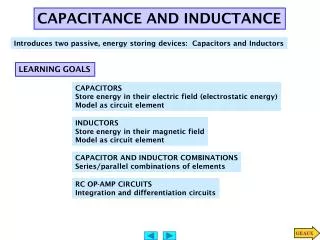
Main Topics • Transporting Energy. • Counter Torque, EMF and Eddy Currents. • Self Inductance • Mutual Inductance
Transporting Energy I • The electromagnetic induction is a basis of generating and transporting electric energy. • The trick is that power is delivered at power stations, transported by means of electric energy (which is relatively easy) and used elsewhere, perhaps in a very distant place. • To show the principle lets revisit our rod.
Moving Conductive Rod VIII • If the rails are not connected (or there are no rails), nowork in done on the rod after the equilibrium voltageis reached since there is nocurrent. • If we don’t move the rod but there is a current I flowing through it, there will be a force pointing to the left acting on it. We have already shown that F = BIl.
Moving Conductive Rod IX • If we move the rod and connect the rails by a resistorR, there will be current I = /R from Ohm’s law. Since the principle of superposition is valid, there will also be the force due to the current and we have to deliverpower to move the rod against this force: P = Fv = BIlv = I, which is exactly the powerdissipated on the resistorR.
Counter Torque I • We can expect that the same what is valid for a rod which makes a translation movement in a magnetic field is also true for rotation movement. • We can show this on rotating conductive rod. We have to exchange the translation qualities for the rotation ones: P = Fv = T
Counter Torque II • First let us show that if we run current I through a rod of the length l which can rotate around one of its ends in uniform magnetic field B, torqueappears. • There is clearly a force on every dr of the rod. But to calculate the torque also r the distancefrom the rotation center must be taken into account, so we must integrate.
Counter Torque III • If we rotate the rod and connect a circular rail with the center by a resistorR, there will be current I = /R. Due to the principle of superposition, there will be the torque due to the current and we have to deliverpower to rotate the rod against this torque: P = T = BIl2/2 = I, which is again exactly the powerdissipated on the resistor.
Counter EMF I • From the previous we know that the same conclusions are valid for linear as well as for rotating movement. So we return to our rod, linearly moving on rails for simplicity. • Let us connect some inputvoltage to the rails. There will be current given by this voltage and resistance in the circuit and there will be some force due to it.
Counter EMF II • After the rod moves also EMF appears in the circuit. It depends on the speed and it has opposite polarity that the input voltage since the current due to this EMF must, according to the Lenz’s law, oppose the initial current. We call this counterEMF. • The result current is superposition of the original current and that due to this EMF.
Counter EMF III • Before the rod (or any other electro motor) moves the current is the greatestI0 = V/R. • When the rod moves the current is given from the Kirchhof’s law by the difference of the voltages in the circuit and resistance: I = (V - )/R = (V – vBl)/R • The current apparently depends on the speed of the rod.
Counter EMF IV • If the rod was without any load, if would accelerate until the induced EMF equalsto the input voltage. At this point the currentdisappears and so does the force on the rod so there is nofurtheracceleration. • So the finalspeedv depends on the applied voltage V. • Now, we also understand that an over-loaded motor, when it slows too much or stops, can burn-out due to largecurrent. Motors are constructed to work at some speed and withstand a certain current Iw< I0.
Eddy Currents I • So far we dealt with one-dimensional rods totallyimmersed in the uniform magnetic field. • But if the conductor must be considered as two or threedimensional and/or it is notcompletelyimmersed in the field or the field is non- uniform a new effect, called eddy currents appears.
Eddy Currents II • The change is that now the induced currents can flowwithin the conductor. They cause a forces opposing the movement so the movement is attenuated or power has to be delivered to maintain it. • Eddy currents can be used for some purposes e.g. smoothbraking of hi-tech trains or other movements.
Eddy Currents III • But eddy currents produce heat so they are source of powerloses and in most cases they have to be eliminated as much as possible by special construction of electromotor frames or transformer cores e.g. laminating.
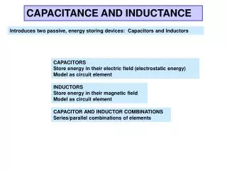
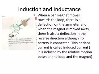
The Self Inductance I • We have shown that if we connect some input voltage to a free conductive rod immersed in external magnetic field an EMF appears which has the opposite polarity then the input voltage. • But even a circuit of conducting wire without any external field will behave qualitatively the very same way.
The Self Inductance II • If some current already flows through such a wire, the wire is actually immersed in the magnetic field produced by its own current. • If we now try to change the current we are changing this magneticfield and thereby the magnetic flux and so an EMF is induced in a direction opposing the change. • If we make N loops in our circuit, the effect is increased N times!
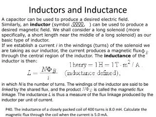
The Self Inductance III • We can expect that the induced EMF in this general case depends on the: • geometry of the wire and material properties of the surrounding space • rate of the change of the current • It is convenient to separate these effects and concentrate the former into one parameter called the (self) inductanceL.
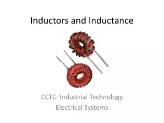
The Self Inductance IV • Then we can simply write: • We are in a similar situation as we were in electrostatics. We used capacitors to set up known electricfield in a given region of space. Now we use coils or inductors to set up known magneticfield in a specified region. • As a prototype coil we usually use a solenoid (part near its center) or a toroid.
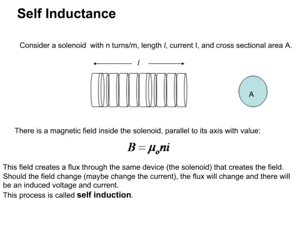
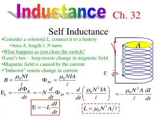
The Self Inductance V • Let’s have a long solenoid with N loops. • If some current I is flowing through it there will be the same flux m1passing through each loop. • If there is a change in the flux, there will be EMF induced in each loop and since the loops are in series the total EMF induced in the solenoid will be N times the EMF induced in each loop. • We use Faraday’s law slightly modified for this situation and previous definition of inductance.
The Self Inductance VI • If N and L are constant we can integrate and get the inductance: • The unit for magnetic flux is 1 weber 1 Wb = 1 Tm2 • The unit for the inductance is 1 henry 1H = Vs/A = Tm2/A = Wb/A
The Self Inductance VII • The flux through the loops of a solenoid depends on the current and the field produced by it and the geometry. In the case of a solenoid of the length l and cross section A and core material with r: • In electronics compomemts having inductance inductors are needed and are produced.
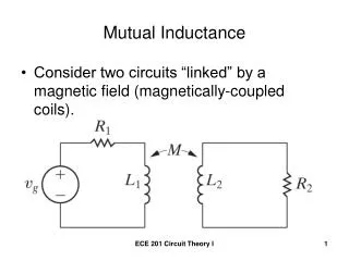
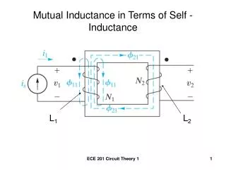
The Mutual Inductance I • In a similar way we can describe mutualinfluence of two inductances more accurately total flux in one as a function of currentin the other. • Let us have two coils Ni, Ii on a common core or close to each other. • Let 21 be the flux in eachloop of coil 2 due to the current in the coil 1.
The Mutual Inductance II • Then we define the mutualinductanceM21 as total flux in all loops in the coil 2 per the unit of current (1 ampere) in the coil 1: M21 = N221/I1 I1M21 = N221 • EMF in the coil 2 from the Faraday’s law: 2 = - N2d21/dt = - M21 dI1/dt • M21 depends on geometry of both coils.
The Mutual Inductance III • It can be shown that the mutual inductance of both coils is the sameM21 = M12 . • The fact that current in one loop induces EMF in other loop or loops has practicalapplications. It is e.g. used to power supply pacemakers so it is not necessary to lead wires through human tissue. But the most important use is in transformers.
Homework • No homework today!
Things to read and learn • This lecture covers: Chapter 29 – 5, 6; 30 – 1, 2 • Advance reading: Chapter 26-4; 29 – 6; 30 – 3, 4, 5, 6
Rotating Conductive Rod • Torque on a piece dr which is in a distance r from the center of rotation of a conductive rod l with a current I in magnetic field B is: • The total torque is: ^