Booting an x86
280 likes | 302 Views
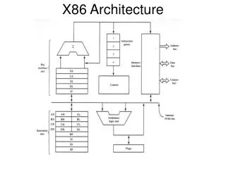
Booting an x86. Bare bones x86 system. Basic x86 system is just a CPU + memory CPU executes instructions loaded from memory Operates on data read/written to/from memory Fundamental operation: memory loads/stores Understanding the x86 starts with understanding how it accesses memory

Booting an x86
E N D
Presentation Transcript
Bare bones x86 system • Basic x86 system is just a CPU + memory • CPU executes instructions loaded from memory • Operates on data read/written to/from memory • Fundamental operation: • memory loads/stores • Understanding the x86 starts with understanding how it accesses memory • This involves a journey through time…
X86 Memory accesses • X86 uses a segment + MMU model of access • Specifics change based on operating mode RAM Program Logical Address (Virtual Address) Segmentation MMU Linear Address Physical Address
x86 Segments • CS = Code Segment • Where instructions are read from • DS = Data Segment • Default for most data operations • SS = Stack Segment • Where stack operations are performed • ES, FS, GS = Auxiliary segments • Explicit or implicitly specified by instructions • Accessed via special registers • 16 bit “Selectors” • Identify the segment to the hardware MMU • Functionality depends on CPU operating mode
X86 control • Operating modes managed by set of control registers
X86 control • Operating modes managed by set of control registers Advanced CPU features Paging Control Basic features
X86 as a time machine • Every time you hit the power button, the system jumps back to the 1980s • System initializes as a 1982 IBM PC compatible machine • 16 bit CPU • 20 bit memory addressing • 640KB RAM • 16 color 640x200 framebuffer video, 80x25 text mode • As system boots it travels forward to modern day • 64 bit CPU (operands and addresses) • 3TB RAM • integrated GPU(s)
1980s: Real Mode • Early PC’s depended on BIOS for hardware interactions • Standard library • Implemented as Real Mode code • 16 bit instructions • Loaded into memory via on board ROM • Customized by the system OEM • All x86 CPUs start execution at 0xffff0 • Where is that? • 1MB of available memory • On a 16 bit architecture?
Real Mode (16 bits) • Segment registers act as base address • 16 bits • Segment size = 64K (216) • Translation: • physical addr = (segaddr << 4) + logical addr • x86 init values: • CS: 0xf000 • IP: 0xfff0 • Goal when in Real Mode: • Get Out of Real Mode • First thing OS does is transition to Protected (32 bit) mode
1990s: Protected mode • Introduced in Intel 80286 (1982) • Became really usable in 80386 (1985) • OS Support only really appeared in early 1990s • Windows 3.0 (1990), Linux (1991) • Features • 32 bit CPU (operands and addresses) • Up to 4GB addressable memory • Optional paging support (not until Windows 95)
32 bit Memory Map • 32 bit addresses • Up to 4GB (232) • Top of memory used by hardware again • “Who would ever need more than 3GB of memory?” • BIOS is still there • Why? • Is it still useful?
Protected Mode (32 bits) • Segment information now stored as a table • GDT (Global Descriptor Table) • Where is the GDT? • Array of segment descriptions (base, limit, flags) • Segment registers now indicate array index • Segment registers select segment descriptor • CS points to Code Segment descriptor in GDT • Still 16 bits • How does Linux use segments? • Check architecture manuals
Entering Protected mode • Initialize hardware data structures in memory • Global Descriptor Table (GDT) • Segment table • lgdt [memory address of 48 bit descriptor that points to GDT] • Interrupt Descriptor Table (IDT) • lidt[memory address of 48 bit descriptor that points to IDT] • Task Segment Selector (TSS) • ltr [selector value that points to TSS entry in GDT] • Set protected mode bit in CR0 • Immediately long jump to new CS segment and 32 bit eip • ljmp <cs>:<rip> • movl%cr0, %eax • orl$0x1, %eax • movl%eax, %cr0
Page Translation • How are virtual addresses translated to physical addresses • Upper bits of address designate page number 12 Bits 20 Bits 4K Pages Page Number Page Offset Virtual Address Page Table Page Base Address Page Offset Physical Address • No comparison or addition: Table lookup and bit substitution • 1 page table per process: One entry per page in address space • Base address of each page in physical memory • Read/Write protection bits • How many entries in page table?
Combine paging and segmentation • Structure • Segments correspond to logical units: code, data, stack • Segments very in size and are often large • Each segment contains one or more (fixed-size) pages • But no longer needs to be contiguous • Multiple ways to combine them: • System 370: Each segment got own page tables Seg # (4 bits) Page # (8 bits) Page offset (12 bits) Why 12 Bits? • x86: First calculate segment offset then do page table lookup • logical address -> linear address -> physical address
Protected Mode + Paging • Segmentation -> Paging -> Physical address • Every address in a page table points to a physical address • Virtual addresses are only an INDEX into page tables • Page size: 4KB • Data and page table pages • Page table page? • 1024 entries per page table page • 2 Level Page Tables • Page tables set via CR3 (What is this?) • Top Level: Entire 4GB of virtual address space • 2nd level: 4MB of virtual address space • Large Pages • Contiguous mappings of virtual addresses to physical addresses
Protected Mode w/ Paging • Paging is a separate (optional) mode in 32bit x86 • Almost always enabled in a modern OS • Initialization • Setup Page Table to use • movl <physical address of page table>, %cr3 • Enable Paging • movl %cr0, %eax • orl$0x80000000, %eax • movl%eax, %cr0
2000s - today: Long mode • Not designed by Intel • Intel wanted to start over with Itanium • AMD hacked together a 64 bit mode for their CPUs • Supported backwards compatibility with x86 • Itanium failed, forcing Intel to adopt AMD’s design • Result: x86_64 or long mode • (or IA-32e mode if you’re Intel)
Long Mode (64 bits) • Segments no longer used for address calculation • Present but must be set to a flat model • Needed because they define the protection level of the CPU (CPL) • Paging must be turned on • Addresses now 64 bits • But pages are still 4KB • Page table hierarchy now has 4 levels • Check architecture manuals • Page table pages now only include 512 entries • Last level page table only covers 2MB of addresses
Enabling Long Mode • Bit more complicated • New control register: EFER MSR • MSR = Model Specific Register • Sort of like lots of control registers specific to a given micro-arch • Accessed with special instructions wrmsr/rdmsr • Each MSR is assigned an ID used with wrmsr/rdmsr • wrmsr/rdmsr • 64 bit control register values stored in separate address space • MSRs identified by 32 bit Register address • Must be loaded into %ecx before each MSR operation • Actual register values read/written via %edx:%eax • %eax-> Low 32 bits • %edx -> High 32 bits
Enabling Long Mode • Bit more complicated Start in Protected Mode with paging disabled Turn on PAE mode in CR4 (large memory support for 32 bit systems) Load CR3 with page table Set LME bit in EFER Enable Paging in CR0 Hardware Transitions to Long Mode Reload GDT, IDT, TR, etc with 64 bit versions • movl $0c0000080, %ecx • rdmsr • orl$0x00000100, %eax • wrmsr