Download
1 / 14
180 likes | 840 Views
VOR Navigation. Richard Champion. VOR Navigation. Aim To learn how to use V HF O mnidirectional R ange (VOR) equipment as an aid to visual navigation. Objective

E N D
VOR Navigation Richard Champion
VOR Navigation • Aim • To learn how to use VHF OmnidirectionalRange (VOR) equipment as an aid to visual navigation. • Objective • By the end of this briefing, you should be able to tune and identify VORs, intercept and track a VOR radial, fix your position using two VORs, use a VOR to avoid controlled airspace and accurately interpret VOR indications. • Airmanship • Lookout (esp near a beacon). Accurate navigation. Avoiding airspace busts • Agenda • The VOR • The Course Deviation Indicator (CDI) • Tune and identify • Intercept and track • Adjusting for wind • Position fix • Setting a guard rail • Interpretation • Summary
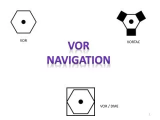
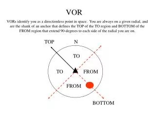
The VOR Transmitter • Depicted like this on charts:- • The Transmitter broadcasts two signals:- • A constant phase signal which is identical in all directions • A reference signal with a varying phase, depending on direction from the beacon. • Equipment on the aircraft measures the phase difference between the two signals and interprets this as a radial from the beacon. • These radials can be pictured as spokes radiating from the centre, each spoke representing a different QDR (magnetic bearing from the station). • VORs are oriented with Magnetic North. • VHF reception is line of sight. Maximum range will depend on the Altitude of the receiving aircraft. • A 3 character Morse Code identifier is also broadcast. • VORs are often co-located with Distant Measuring Equipment (DME) but the systems are independent.
The Course Deviation Indicator (CDI) TO flag. Indicates that the selected bearing is TO the VOR NB This does NOT mean that the aircraft is moving towards the VOR The Selected Radial is shown here Course Deviation Needle Shows how far off selected radial you are TO FM flag. Indicates that the selected bearing is FROM the VOR Again, this does NOT mean that the aircraft is flying away from the VOR FM Omni Bearing Selector Use to select radial OBS Deviation scale. 2 Degrees per mark
CDIs come in all shapes and sizes Katana DA20 Cessna 172 Cessna 172
Select, Tune and Identify 115.100 Select appropriate VOR from chart Note the frequency Note the Ident Write Morse code Ident out Tune Nav box standby Frequency Flip flop to Active Listen to Morse Ident B I G NAV 1 112.35 115.10 112.35 115.10 Pull Ident
Intercept and Track a VOR radial • Current position: • Approaching Bough Beech • Heading 100° • On 160° radial from BIG • Select the140°radial on the CDI • Turn right 10° to establish a 30° intercept angle. • Fly towards the radial • Observe the CDI needle moving toward the centre. • Anticipate interception by a few degrees • (4° if close/fast, 2° if far/slow) • Turn onto 140° (or wind adjusted heading if known). TO FM
Adjusting for Wind 230/15 Use your prior knowledge of the wind to estimate a wind correction angle. If in doubt, use 5° into wind as a starting point. Adjust heading by estimated wind correction angle. Continue flight, monitor CDI needle. If CDI needle moves, adjust heading sufficiently to stop further movement. Note new heading. Re-acquire the radial by centring the needle using 5 degree heading changes. Return to wind adjusted heading Monitor and adjust as required. FM
Setting a Guard Rail TO FM NAV 1 To avoid infringing Gatwick Airspace:- 123.45 123.45 Pull Ident Select the 270 radial from MAY 2. Tune and Identify MAY, Set 270 on CDI 3. Monitor CDI. Maintain Fly Right Signal OBS 117.90 117.90
Position Fix TO FM NAV 1 6. Repeat with second VOR 3. Listen to Morse ID Twist OBS until needle is centred with FM flag Enter first VOR frequency 5. Draw Radial on chart 2. Flip Flop to active 123.45 123.45 Pull Ident OBS 117.30 117.30 115.10 115.10
Interpreting the CDI 060° TO A TO Answer B NAV 1 117.90 123.45 Pull Ident B A, B or C? OBS C F
Interpreting the CDI A Answer C FM NAV 1 117.90 123.45 Pull Ident B A, B or C? OBS C F
Interpreting the CDI A TO Answer A NAV 1 130° TO 117.90 123.45 Pull Ident B A, B or C? OBS C F
Summary • We have learned:- • What a VOR is • What the CDI does • How to Tune and Identify a VOR • How to intercept and track a radial to or from a VOR • How to fix your position • How to set a guard rail to keep you out side of controlled airspace or hazard • How to interpret what the CDI is telling us