Download

1 / 12
1.46k likes | 4.09k Views
Applications of OP-AMP. Introduction. Operational amplifier using IC's is inexpensive, versatile and easy to use. For this reason they are used not only for negative feedback amplifiers but also used for wave shaping, filtering and mathematical operations. Some commonly used applications are

E N D
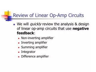
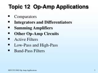
Introduction • Operational amplifier using IC's is inexpensive, versatile and easy to use. For this reason they are used not only for negative feedback amplifiers but also used for wave shaping, filtering and mathematical operations. Some commonly used applications are • Inverting Amplifier • Summing Amplifier • Non-Inverting Amplifier • Voltage Follower • Comparator • Zero Cross Detector • Integrator • Differentiators www.ustudy.in
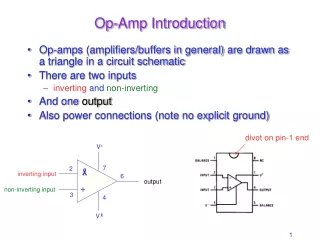
An Inverting Amplifier Using Op-Amp • The non Inverting input is grounded. • A “feedback network” composed of resistors R1 and R2 is connected between the inverting input, signal source and amplifier output node, respectively. This amplifier uses voltage shunt negative feed back for controlling the gain It looses high input resistance property because of shunt mixing at i/p There exist a virtual short circuit between the 2-inputs of Op-Amp. The inverting i/p is at virtual ground www.ustudy.in
Inverting Amplifier : Voltage Gain Av • The negative sign of voltage gain implies that there is a 1800 phase shift between input and output signals. • The gain magnitude can be greater than 1 if R2 > R1 • The gain magnitude can be less than 1 if R1 > R2 • The inverting input of the Op Amp is at ground potential (although it is not connected directly to ground) and is said to be at virtual ground. But is= i2 and v- = 0 (since vid= v+ - v-= 0) and www.ustudy.in
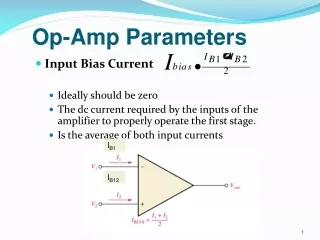
Inverting Amplifier: Input and Output Resistance Rout is found by applying a test current (or voltage) source to the amplifier output and determining the voltage (or current) after turning off all independent sources. Hence, vs = 0 But i1=i2 Since v- = 0, i1=0. Therefore vo = 0 irrespective of the value of io . www.ustudy.in
Summing (Scaling) Amplifier Because the op-amp Inv-Input is at virtual ground the multiple inputs are treated as separate inputs. www.ustudy.in
The Non-inverting Amplifier • The input signal is applied to the non-inverting input. • A part of the output signal is fed back to the inverting input. • There exist the virtual short circuit between two input terminals of Op Amp, v1 is same as vs www.ustudy.in
Voltage follower • The voltage follower, also called a buffer, provides a high input impedance, a low output impedance, and unity gain. As the input voltage changes, the output and inverting input will change by an equal amount. The voltage gain of this configuration is unity or 1. • This circuit is useful though it does not have any voltage gain. Since it has a high input impedance, it makes an excellent isolation amplifier. www.ustudy.in
The inverting amplifier exhibits a much lower input impedance due to the virtual ground created by the negative feedback. • A high impedance signal source will suffer loading effects when connected to such amplifier and therefore it is sometimes necessary to isolate the signal source by connecting it to a voltage follower to the next stage. www.ustudy.in
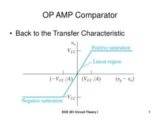
Comparator • Compares two voltages and switches its output to indicate which voltage is larger. • (where Vs is the supply voltage and the opamp is powered by + Vs and − Vs.) www.ustudy.in
Op-Amp Integrator The inverting input is at virtual ground. Hence, Applying KCL at the inverting input i1+i2 = 0 www.ustudy.in
The Difference Amplifier • This circuit is also called a differential amplifier, since it amplifies the difference between the input signals. • Rin2 is series combination of R1 and R2 because i+ is zero. • For v2=0, Rin1= R1, as the circuit reduces to an inverting amplifier. • For general case, i1 is a function of both v1 and v2. Since v-= v+ For R2= R1 Also, www.ustudy.in