Download
1 / 51
510 likes | 698 Views
Mercury G3 Service Tool Training Overview. Connect your G3 cable USB to computer and install drivers so cable can communicate with G3

E N D
Mercury G3 Service Tool Training Overview • Connect your G3 cable USB to computer and install drivers so cable can communicate with G3 • If connecting to Axius or Zeus models, connect the 10 Pin on the G3 cable to the standard 6 or 8 way junction box for communication. On Axius it could also be plugged into the 10 Pin engine connection by removing the weather cap. (Yellow resistor on DTS engines) • EC Engine connections, remove Yellow terminator resistor on engine harness. Use a 10 pin female to female connection to a 4 way J-box, install Yellow terminator from engine harness on to 4 way J-box. Female to female adaptor from 4 way to engine harness and G3 cable plugs into 4 way. You must keep the terminators on the CAN bus!
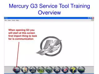
Mercury G3 Service Tool Training Overview When opening G3 you will start at this screen first import thing to look for is communication
Red lights on both CAN P and CAN H indicate that the cable is not detected by G3 (check connection at USB on Computer)
Yellow lights on CAN P and CAN H indicate the cable is detected but no response from Modules on CAN bus. Check power supply
Cable Connection problem One CAN Bus is not detected in cable. Check Settings on Cable look at following slide.
Click on YES to change options this will allow channel change on CAN H since it shows to not be set. You would select Ch. 1 with CAN P mapping on Ch. 0
When you click on yes you will get this Options box which will allow you to set channel. Set CAN H to Ch. 1 and click save to apply.
G3 cable is now detected by G3 tool. It is not communicated at this point, only showing that it G3 tool sees cable.
G3 is now communicating on CAN Bus to ping modules and you are ready to select the EBOM to establish communication to Engine/Helm/TVM for Axius or just Engine for Catalyst. EBOM stands for Electronic Bill of Material and each contains all software sets for communication
As the tool is pinging modules the EBOM will start to populate with the proper build of which you can communicate with and see data stream information from the module(s)
Under 6.2 Bravo the tool has indicated there are 10 modules on the CAN Bus. You can select the drop down box to see the module City ID’s that are in this selection. You will then click on the select button to pick this data set to communicate with.
The next button after EBOM is Configuration which is used for the vessel set up.
Start Here The Compass Calibration Wizard will walk you through all the steps to properly calibrate the compass and complete the Validate Compass Configuration. You can start there or start at the compass Linearization tab if magnetic interference is a known issue in the vessel area.
If starting at Compass Linearization you will walk through the remaining steps as well to Validate Compass Configuration.
From the main configuration screen you will choose Helm Configuration to set up helms. In the helm config menu you will see the City ID’s on the CAN bus for CCM’s that are configured.
On a new Axius set up that was not configured there would only be a Starboard Outside CCM. The software establishes a city ID 92 on the Helm Set Up as there is only one CCM SRZ file. Helm set up will need to be completed to see a City ID 92 on Port Outside.
Current Configuration not set up as City ID 91 is in Red. Set number of engines as shown on next slide.
After clicking next the Turn Keys Off screen will appear, turn keys off, then click OK
Helm has been adapted, click the OK button to proceed with Lever Configuration.
Go to Lever Adapt, choose lever type and set shift polarity and adapt all if setting up a new vessel, then click the start button. Make sure helm selection is on appropriate Helm for configuration.
The warning pop up window will appear when you click start telling you that handles must be completely adapted for engines to start.
From Step 1 through Step 6 you will move both levers from RWOT to FWOT and then back to Neutral. After each step you will click the Next button at bottom right of screen
This pop up window will appear, turns keys off then press the OK button to continue.
Once Helm Config is completed, you will do a steering wheel adapt. If steering wheel adapt is not completed before Drive Initialization a WheelposAbsolute_Diff Fault may appear.
Select # of engines by selecting drop down box # of Helms then Next
Select Helm # and proceed in this slide there is no CCM online so process is not allowed
Trackpad Configuration will allow you to see current City ID locations as well as reconfigure the City ID locations
Once in Trackpad Configuration it will show you current trackpads on CAN P and CAN H with City ID’s. You can retore city id or assign track pads to new city ID’s. All ERC Track pads are on CAN P while Axius Precision Pilot screens are on CAN H
Drive Alignment screen is an On Water set up, vessel must be in water to complete
Manual Drive alignment is usually done when drives are installed at OEM. It may need configured at Dealer if drives are removed or transoms replaced. The Vessel must be out of the water for this set up. 4 way valve is unlocked on TVM to allow drive to move by hand. It will require some force to move drive.
Drive initialization will need to be completed if on key up a TVM Non-Critical fault appears or if linear sensors have been replaced, or if software is updated. G3 is not yet capable of installing Current table shift or hysteresis values.
Select drive to initialize either port or starboard or both. On small block applications only select one drive if the opposite drive location is center or outward of center position as drives could touch. It is best to have engines above idle speed and make sure battery voltage is sufficient to complete test.
Import function is to import the boat personality. This was done before with a USB into the vesselview. One difference to be noted is that the personality name will not appear in VesselConfig – All Modules screen
Module data screen will allow you to see all modules on CAN Bus and look at Data Stream, Faults and Freeze Frame and Run History on Engine PCM’s.
Active Tests screen, only tests that are highlighted are function so tests will be limited to module capability. Not Available Active Not Available This is only a screen shot for demonstration, Tests available are dependent on the PCM capabilities.
Print screen option, data logging is not available on first release but print screen is. You can click on this option and it will take a snap shot of data and file to predetermined location. Data logging will be available on later updates.
Show Options allows you to change CAN Channel mapping or Screen Print output path.
Help Screen (?) allows you to see G3 System Specifications along with Vessel Specifications which is help information on Chart plotters SW and Install.