Preparing Variable kVp Technique Charts
Preparing Variable kVp Technique Charts. By Prof. Stelmark. Anatomic Programming

Preparing Variable kVp Technique Charts
E N D
Presentation Transcript
Preparing Variable kVp Technique Charts By Prof. Stelmark
Anatomic Programming Anatomic programming, or anatomically programmed radiography (APR), refers to a radiographic system that allows the radiographer to select a particular button on the control panel that represents an anatomic area; a preprogrammed set of exposure factors is displayed and selected for use. APR is controlled by an integrated circuit or computer chip that has been programmed with exposure factors for different projections and positions of different anatomic parts. Once an anatomic part and projection or position has been selected, the radiographer can adjust the exposure factors that are displayed.
APR and AEC are not related in their functions, other than as systems for making exposures. However, these two different systems are commonly combined on radiographic units because of their similar dependence on integrated computer circuitry. APR and AEC often are used in conjunction with one another. A radiographer can use APR to select a projection or position for a specific anatomic part and view the kVp, mA, and exposure time for manual technique.
When APR is used in conjunction with AEC on some radiographic units, the APR system not only selects and displays manual exposure factors but also selects and displays the AEC detectors to be used for a specific radiographic examination. For example, pressing the Lungs PA button results in selection of 120 kVp, the upright Bucky, and the two outside AEC detectors. As with AEC, APR is a system that automates some of the work of radiography. However, the individual judgment and discretion of the radiographer is still required to use the APR system correctly for the production of optimal quality image.
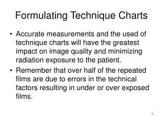
Exposure Technique Charts and Radiographic Quality A properly designed and used technique chart standardizes the selection of exposure factors to help the radiographer produce consistent quality radiographs while minimizing patient exposure.
Exposure Technique Charts and Digital Imaging Systems Exposure technique charts are just as important for digital imaging because digital systems have a wide dynamic range and can compensate for exposure technique errors. Technique charts should be developed and used with all types of radiographic imaging systems to maintain patient radiation exposure as low as reasonably achievable (ALARA).
CONDITIONS A technique chart presents exposure factors that are to be used for a particular examination based on the type of radiographic equipment. Technique charts help ensure that consistent image quality is achieved throughout the entire radiology department; they also decrease the number of repeat radiographic studies needed and therefore decrease the patient's exposure.
Technique charts do not replace the critical thinking skills required of the radiographer. The radiographer must continue to use individual judgment and discretion in properly selecting exposure factors for each patient and type of examination. The radiographer's primary task is to produce the highest quality radiograph while delivering the least amount of radiation exposure.
Technique charts are designed for the average or typical patient and do not account for unusual circumstances. These atypical conditions require accurate patient assessment and appropriate exposure technique adjustment by the radiographer • Pathology • Cast and splinters • Body habitus
Technique Chart Formulation Requirements: • A technique chart should be established for each x-ray tube including portable unit. • Departmental standards for radiographic quality should be established. • The radiographic equipment for which the charts are developed must be calibrated. • Image processing must be consistent throughout the department to produce the proper radiographic density and contrast.
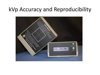
Accurate measurement of part thickness is critical to the effective use of exposure technique charts. Calipers are devices that measure part thickness and should be readily accessible in every radiographic room. In addition, the technique chart should specify the exact location for measuring part thickness. Part measurement may be performed at the location of the CR midpoint or the thickest portion of the area to be radiographed. Errors in part thickness measurement are one of the more common mistakes made when one is consulting technique charts.
Factors Standardized in a Technique Chart: Anatomic part Grid ratio Kilovoltage peak Milliamperage Central ray location Part thickness and measuring point Type of image receptor Position or projection Focal spot size Source-to-image receptor distance
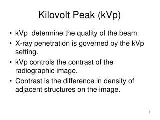
VARIABLE KVP/FIXED MAS TECHNIQUE CHART The variable kVp/fixed mAs technique chart is based on the concept that kVp can be increased as the anatomic part size increases. Specifically, the baseline kVp is increased by 2 for every 1-cm increase in part thickness, whereas the mAs is maintained. The baseline kVp is the original kVp value predetermined for the anatomic area to be radiographed. The baseline kVp is then adjusted for changes in part thickness.
Characteristics: • Only kVpvaries • Uses lowest kVp to penetrate the part • All factors are constant except for kVp • 2 kVp for every 1 cm increase • Produces highest radiographic contrast • Produces shortest scale of contrast • Results in highest patient dose • Increase in tube heat load
Groups: • Extremities • Abdomen and Pelvis • Lateral Cervical Spine • Lateral Thoracic Spine • Lateral Lumbar Spine • Chest • Skull • Sinuses • Contrast - Barium
Variable kVp technique charts may be more effective for pediatric patients or when small extremities are being imaged.
Determine the correct kVp • Minimum kVp ( single phase) = [part thickness (cm) x 2] + 30 kVp • Minimum kVp ( Triple phase) = [part thickness (cm) x 2] + 25 kVp • Determine the correct mAs • Select three possible mAs settings: • Expected mAs • Half of the expected mAs • Double the expected mAs
Accuracy of measurement is critical with variable kVp/fixed mAs technique charts