Download
1 / 32
320 likes | 478 Views
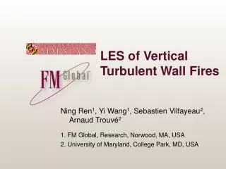
LES of Vertical Turbulent Wall Fires. Ning Ren 1 , Yi Wang 1 , Sebastien Vilfayeau 2 , Arnaud Trouvé 2 1. FM Global, Research, Norwood, MA, USA 2. University of Maryland, College Park, MD, USA. Background. Industrial-scale fire tests Reduce fire loses Expensive Limited configurations

E N D
LES of Vertical Turbulent Wall Fires Ning Ren1, Yi Wang1, Sebastien Vilfayeau2, Arnaud Trouvé2 1. FM Global, Research, Norwood, MA, USA 2. University of Maryland, College Park, MD, USA
Background • Industrial-scale fire tests • Reduce fire loses • Expensive • Limited configurations • Fire modeling • Understand physics • Reduce large scale tests • Challenges • Multi-physics • Multi-phases 6 m
Tools – FireFOAM • Open-source fire model (FM Global) • www.fmglobal.com/modeling (2008-Present) • Based on OpenFOAM • A general-purpose CFD toolbox (OpenCFD, UK) • Main features • Object-oriented C++ environment • Advanced meshing capabilities • Massively parallel capability (MPI-based) • Advanced physical models: • turbulent combustion, radiation • pyrolysis, two phase flow, suppression, etc.
Background • Industrial-scale Fire Test • Multi-physics interaction • Difficult to instrument • Vertical wall fire is a canonical problem
Background • Experiments • Orloff, L., et.al (1974) PMMA • Ahmad, T., et.al (1979) • Markstein, G.H., de Ris, J. (1990) • de Ris, J., et.al (1999) • Modeling • Tamanini, F. (RANS,1975) PMMA • Kennedy, L.A., et.al (RANS,1976) • Wang, Y.H., et.al (RANS, 1996) • Wang, Y.H., et.al (FDS, 2002) • Xin, Y. (FDS, 2008) Orloff, L, et.al (PMMA) • Challenges • High grid requirement • Buoyancy driven • Mass transfer • Reacting boundary flow
Experiments – (J. de Ris et al., FM, 1999) (J. de Ris et al., Proc. 7th IAFSS, 2002) • Prescribed flow rates • Propylene • Methane • Ethane • Ethylene • Water cooled vertical wall • Diagnostics • Temperature • Radiance • Heat flux • Soot depth
Grid requirement • Momentum driven flow (Piomelli et al., 2002) • Natural convection (Holling et al., 2005) • Wall Fires • 10~20 cells across the flame • 3mm to start 2 cm
Mesh and B.C. • Base line – 3 mm grid • ΔY ~ 3 mm, ΔX ~ 7.5 mm, ΔZ ~ 7.7 mm (ΔX :ΔY :ΔZ ~ 2.5:1:2.5) • 0.8 M cells, CFL = 0.5 • 1.5, 2, 3, 5, 10, 15 and 20 mm • B.C. • Cyclic (periodic) in span-wise • Entrainment BC at the side • Fixed temperature, T = 75 ˚C • Propylene • 8.8, 12.7, 17.1, 22.4 g/m2s
Turbulence Model WALE Model K-equation model Wall adaptive local eddy viscosity model Zero for pure shear flow O(y3) near wall scaling Two deficiencies: Laminar region with pure shear Wrong scaling at near wall region O(1) instead of O(y3) No need to calculate ksgs
Wall-Adaptive Local Eddy Viscosity K-Eqn Model WALE Model
Combustion Model • Eddy Dissipation Concept (EDC model) • Mixing controlled reaction K-equation model WALE model
Combustion Model • Eddy Dissipation Concept (EDC model) • Mixing controlled reaction Turbulence reaction rate Diffusion reaction rate
Radiation Model • Fixed radiant fraction • Finite volume implementation of Discrete Ordinate Method (fvDOM) • Optically thin assumption • Soot/gas blockage (χrad is reduced by 25%)
Flame topology K K m/s m/s m/s m/s span-wise wall-normal stream-wise
Flame topology Wallace, J.M., 1985 kg/m/s kg/m/s Q, wall-normal view
Heat flux – (de Ris Model) Soot volume fraction Soot depth Blockage Side-wall Flame radiation temperature Flame emissivity Heat transfer coefficient Fuel blowing effect
Grid Convergence (=17.1 g/m2s, C3H6) Fully Turbulent Fully Turbulent Fully Turbulent
Convective Heat Flux: Blowing Effect 17.1g/m2s Pyrolysis Zone Pyrolysis Zone Flaming Zone Flaming Zone
Summary and future work • Summary • Near wall turbulence and combustion models are important • Good agreements are obtained for wall-resolved modeling • 10~20 cells across the flame are needed • Convective heat flux is important in the downstream flaming zone • Future work • Test soot model for radiation • Improve turbulence and combustion models for coarse-grained modeling • Wall function study
Ongoing work – wall function • Log-Law • Blowing effect (Stevenson, 1963)
Ongoing work – wall function (Δ=15 mm) (17.1 g/m2s, C3H6)
Ongoing work – wall function (Δ=15 mm) Fuel blowing effect
Acknowledgement • John de Ris • Funded by FM Global • Strategic research program on fire modeling
Temperature – Elevation (17.1 g/m2s, C3H6) Inner layer Outer layer
Coarse grid • Convective heat flux • Temperature gradient • Combustion • Radiative heat flux • Combustion
A temporary approach K-equation K-equation, WALE Minimize the influence of combustion Better turbulence & combustion model needed in future