Download
1 / 11
110 likes | 129 Views
Learn about the Nominal Beam Test Coordinate System: its alignment, imperfections, and relation to the Detector Local Coordinate System for HEC and EMEC detectors. Understand coordinate transformations and updated geometry files for precise testing.

E N D
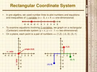
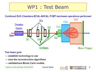
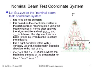
y x Nominal Beam Test Coordinate System • Let S(x,y,z) be the “nominal beam test” coordinate system • It is fixed on the cryostat; • It is based on the coordinate system of the particle track reconstruction using the beam chambers, hence after applying the alignment file and using ytable and xcryo in Athena. The alignment file has been refined by Sven Menke to satisfy the following; • It is a right-handed system with y vertically up and z horizontal in opposite direction to the test beam; • x = y = 0 and z = -64.2 cm is where the beam hits the face of the presampler for ytable = xcryo = Ibend9 = 0. HEC-EMEC beam test geometry
Nominal Beam Test Coordinate System • Known imperfections • Sven has investigated the consistency of the alignment file with beam chamber data and has found the following relations in the y axis: • y (z = 0) = -0.317 cm + 1.065 ytable(cm) • slope in y = 0.000456 – 0.000320 ytable(cm) • This means that the alignment file is not perfect and probably should absorb the –0.317 cm offset; • This means the slope of the fit for ytable = 0 is not 0. This could be absorbed by a shift of –1.43 cm in ytable, or by assuming that the test beam is not truly horizontal. HEC-EMEC beam test geometry
The Detector Local Coordinate System • Let SL(xL,yL,zL) be the detector (HEC or EMEC) local coordinate system • It is a right handed system attached to the detector; • It’s origin is the (ideal or truly pointing) Atlas origin; • zL is in the direction of the test beam. For the EMEC, xL is along the rightmost edge of the beam test module (looking down the beam). zL Atlas beam line zL in page test beam EMEC line of constant HEC-EMEC beam test geometry
The Detector Local Coordinate System • In order to maintain an absolute meaning to the local azimuthal coordinate, the xL axis for the HEC is defined to be the same as the one for the EMEC, assuming the nominal position of the HEC: zL in page HEC layer 3 HEC layers 1 and 2 EMEC HEC-EMEC beam test geometry
z y x The Detector Local Coordinate System • The , , and quantities for a point in SL are defined in the usual way. • Dropping the L subscript and using a cylindrical coordinate system, we obtain the following relations: HEC-EMEC beam test geometry
The Detector Local Coordinate System • The spherical coordinate system variable r is of little use, but for completeness we note the following relations: HEC-EMEC beam test geometry
Coordinate System Transformation • The SLS transformation is obtained using a passive y-convention Euler rotation (Goldstein section 4.4) and a translation HEC-EMEC beam test geometry
convention front face of presampler Coordinate System Transformation • Nominal values • Thanks to Sven Menke, Alexei Maslennikov and Roy for clarifications on various coordinate values • The nominal values are the same for the HEC and for the EMEC HEC-EMEC beam test geometry
Geometry Files • We now have updated geometry files • Thanks to Margret, Richard and Fares Djama for the channel median coordinates, and to Ian for cleaning up the geometry files format; • They contain HEC and EMEC channel “median” coordinates in their respective local coordinate system: • these quantities do not in general denote the geometrical center of a cell. Rather, we have HEC-EMEC beam test geometry
Geometry Files • in the HEC geometry file, the pseudorapidity limits refer to the middle of a module and to the middle z of a family zF (one of the 5 types of pad layouts, 7 in Atlas) . Consider the following schematic (not to scale!) of a HEC family; middle of module HEC-EMEC beam test geometry
Geometry Files this drawing is in the plane of the middle of a HEC module and shows the 7 families and the boundaries passing through the pad boundaries at zF z HEC-EMEC beam test geometry