Download
1 / 25
250 likes | 268 Views
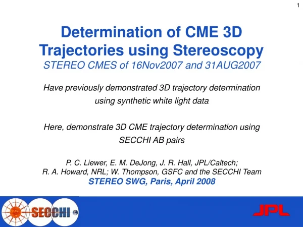
This study demonstrates the determination of 3D trajectories of CMEs using stereoscopy with SECCHI AB pairs. The software validates the results by comparing with LASCO height-time data and shows the ability to track CMEs through multiple FOVs.

E N D
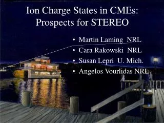
Determination of CME 3D Trajectories using StereoscopySTEREO CMES of 16Nov2007 and 31AUG2007 Have previously demonstrated 3D trajectory determination using synthetic white light data Here, demonstrate 3D CME trajectory determination using SECCHI AB pairs P. C. Liewer, E. M. DeJong, J. R. Hall, JPL/Caltech; R. A. Howard, NRL; W. Thompson, GSFC and the SECCHI Team STEREO SWG, Paris, April 2008
Stereoscopy and STEREO/SECCHI • SECCHI uses World Coordinate System (WCS) solar soft routines to relate image plane coordinates to heliocentric coordinate systems (see W. Thompson, A & A, 2005, MS 4262thom) • Need location of spacecraft A&B (from emphemeris), pixel size (arcsec), and pixel location of Sun-center (xSUN , ySUN). • Each pixel defines a unique ray • In a single 2D image, feature can be anywhere along ray • In 3D, if perfect tiepointing, rays intersect at feature • Triangulation program locates feature at point of closet approach of the two rays
y LOS B SC B x LOS A COR2 - SC B at +20° COR2 - SC A at -20° SC A • Bright localized coronal structures (loops, filaments) can be reconstructed in 3D from SECCHI A+B image pairs using stereoscopy • Because CMEs are so diffuse, stereoscopy on line-of-sight (LOS) coronagraph images gives approximate 3D location of CME “edges” Stereoscopy of CMEs vs Localized Structures Synthetic image pair from hemisphere shell CME model
STEREO CME November 16, 2007 COR2LASCO CME 20072226.092608 - Behind limb for all 3 SC COR2 B COR2 A
COR2 20071116_153754 Determination of 3D CME Trajectories • CME visible in both STEREO A & B with obvious difference in height • ~40.4 separation between A&B on November 16, 2007 • User marks same features on CME in both images of COR2 AB pair • Tiepoints are constrained to lie in epipolar line • Here, tiepointing the leading edge of CME only • Triangulation program finds 3D coordinates in heliocentric system • Time series of 3D reconstructions gives 3D trajectory
3D Reconstruction of CME Leading Edge 7 times - half hour time increments
CME direction Linear Speed Comparison: LASCO V(pos) = 320 km/s STEREO V(3D) = 470 km/s CME Trajectory and Comparison with LASCO Carrington longitudes B= 181° Earth =201 ° A = 221° CME = 315 ° CME in A’s Plane of Sky!
STEREO Prominence & CME August 31, 2007LASCO data gap: only caught trailing end EUVI 304 B EUVI 304 A
STEREO Prominence & CME August 31, 2007LASCO data gap: only caught trailing end COR1 B COR1 A
STEREO CME August 31- September 1, 2007LASCO data gap: only caught trailing end COR2 B COR2 A
3D Reconstruction of Erupting Prominence August 31, 2007 EUVI 304 data from A + B Long filament: pre-eruption Every 2.5 mins during eruption CR Lat = -30º CR Long = 194º B= 131° Earth =143° A = 159°
3D Reconstruction of CME Leading EdgeAugust 31 - September 1, 2007 COR2 data, A + B ~30 min increments COR1 - only lowest reconstruction CR Lat = -20º CR Long = 210º B= 131° Earth =143° A = 159° 20070831_220500 to 20070901_033730
3D Reconstruction of Cavity Leading Edge August 31, 2007 COR1 data, A + B 5 minutes increment About 1 hr total 20070831_204500 to 20070831_215000
3D Reconstructions of Prominence + Leading Edges of both Dark Cavity and CME August 31, 2007 EUV 304, COR1, COR2 data, A + B Various times covering 7 hours Software works across multiple FOVs! Prominence Cavity Leading Edge 20070831_161615 to 20070901_030730 Bright Leading Edge
3D Reconstructions of Prominence + Leading Edges of both Dark Cavity and CME August 31, 2007 EUV 304, COR1, COR2 data, A + B Various times covering 7 hours Note all line up! 20070831_161615 to 20070901_030730
3D Reconstructions of Prominence and Leading Edge of Dark Cavity August 31, 2007 21:25:00 COR1 A + B Shows relation of filament to dark cavity in 3D
Conclusions • Demonstrated that stereoscopy can be used to track CME propagation in 3D • Determined approximate 3D trajectory of 2 STEREO CMEs • Validated software by comparison with LASCO height-time results • Plan further tests by comparison with 3D forward modeling CME reconstruction of Therneisen et al. • Reconstructed three parts of 2007/08/31 STEREO CME • Bright Leading Edge, Dark Cavity Leading Edge, Prominence • Demonstrated ability to track CME through 3 FOVs - EUVI, COR1,COR2 HD SECCHI A & B Daily Quicktime Movies http://solarmuse.jpl.nasa.gov User: Science_Team Pass:secchi07 • Now EUVI 1K by 1K available In Beta test - All telescopes
COR2 - SC B at +20° COR2 - SC A at -20° LOS B Early Test on hemisphere CME for Tiepointing Bright Leading Edge y SC B 60° +20° Result: • Leading Edge at 15.1 Rsun vs actual 15 Rsun • Angle of 72° vs actual 60° x LOS A -20° SC A
Consider Increasing SC Separations with CME in between A&B SC A y x SC B
Consider Increasing SC Separations with CME in between A&B SC A y x SC B
Consider Increasing SC Separations with CME in between A&B SC A y x SC B
Nov 16, 2007 Prom and CME • Limb event for STEREO A - Behind the limb event for LASCO & STEREO B • COR1A shows clear deflection of CME towards equator
COR2 - SC B at +20° COR2 - SC A at -20° • Bright localized coronal structures (loops, filaments) can be reconstructed in 3D from SECCHI A+B image pairs using stereoscopy • Because CMEs are so diffuse, stereoscopy on line-of-sight (LOS) coronagraph images gives approximate 3D location of CME “edges” Stereoscopy of CMEs vs Localized Structures y LOS B SC B x LOS A SC A Synthetic image pair from hemisphere shell CME model