Download

1 / 52
520 likes | 737 Views
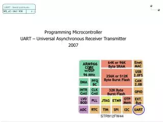
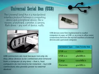
Programming Microcontroller Universal Synchronous Bus (USB) Autumn 2012. 1995: Foundation of the “USB Implementers Forum” (USB IF) http://www.usb.org 1996: First USB specification issue (USB 1.0) Connection of various peripheral devices to a single interface Mouse, keyboard, printer …

E N D
Programming Microcontroller Universal Synchronous Bus (USB) Autumn 2012 USB
1995: Foundation of the “USB Implementers Forum” (USB IF) http://www.usb.org 1996: First USB specification issue (USB 1.0) Connection of various peripheral devices to a single interface Mouse, keyboard, printer … 2000: Specification of USB 2.0 Extension of the speed at 480 M bit/s Possibility to connect hard drives or video devices Overview (story) USB 2
USB is a asymmetrical bus Distinction between USB host (PC) & device Data is transmitted in a serial asynchronous format Baud rate 1.5 M bit/s (Low-Speed) 12 M bit/s (Full-Speed) 480 M bit/s (High-Speed, only for USB 2.0) Overview (generality) USB 3
USB 4 USB bus topology (network) • 127 devices can be connected to the bus (incl. hubs) • Each USB device receives a specific address from the host (PC) • Enumeration
Bus powered hub The total current is obtained from the host (PC) 500 mA are available for the all the connected devices Self powered hub Additional connector for the power supply Each device can consume a maximum of 500 mA USB bus topology (power supply) USB 5
USB cable contains 4 wires VCC (+5V) GND Differential data lines D+ and D- (0 and 3.3 V) Signal rise and fall times www.usb.org USB cable USB 6
USB plugs USB 7
Host / hub must recognize the connected USB device Host / hub begins with the speed detection Pull-up or pull-down resistors USB speed detections (1/2) 8
USB speed detections (2/2) UART - Serial communic. • Distinction between full & fast speed devices • Full speed devices generate a chirp signal (fast toggling) during reset • Host recognize this chirp and switch into high speed • Pull-up resistor is disconnected during this transmission mode
SOP (Start-of-Packet) Transition from the “Idle-State” into the “K-State” First bit of the SYNC-field EOP (End-of-Packet) Data lines are set to low (SE0) USB bus states USB 10
Bus Reset SE0 is driven more than 2.5 ms Suspend (Energy saving mode) USB devices fall asleep when the bus is inactive for 3 ms After 3 ms high-speed devices switch into full-speed mode 100-875 ms after they go into suspend mode Resume Resume sequences wake up the fallen asleep devices Data lines are driven into the K-State during 20 ms USB bus states USB 11
Data transmission begins with LSB (Least Significant Bit) Data encoding is NRZI (Non-Return-To-Zero-Inverted) Data encoding USB 12
Problem Synchronization loss when several high bits must be send Solution Insertion of an additional low bit after the 6th high bit Bit Stuffing USB 13
Control transfer Configuration of the USB device Host sends requests to the device 10% of the bandwidth is reserved for control transfer Interrupt Transfer Transfer of a few amount of data with guaranteed bandwidth Mouse, keyboards etc. Host asks the interrupt endpoints periodically Endpoint specifies the period 90% of the bandwidth is reserved for interrupt & isochronous transfers Interrupt transfers are subject to the USB error detection Transfer types (1/2) USB 14
Bulk transfer (full- & high speed device) Transmission of large amount of data, which are not time critical Printers, scanner & memory-Sticks Transmission in the remaining available bandwidth Isochronous transfer 90% of the bandwidth is reserved for interrupt & isochronous transfers Data are sent every 1 ms frame Devices that require a constant data stream Audio- und video capture devices Transfer types (2/2) USB 15
16 Protocol Layer (OSI Layer 2) • Data are transferred though USB data pipes • Each pipe goes from the host and terminates in an endpoint
Sub address in a USB device with its own FIFO Pipes and endpoints USB 17
18 Type of endpoints • Each USB device has at least one control endpoint (endpoint 0) • Configuration of the USB device • Each endpoint has a predefined FIFO size • All endpoint except endpoint 0 are unidirectional • Each endpoint has a number (address) • IN- endpoints: Address 0x81until 0x8F • OUT- endpoints: Address 0x01 until 0x0F
USB specifies various types of errors CRC check sum (Cyclic Redundancy Code) CRC5: G(X) = X5 + X2 + 1 CRC16 : G(X) = X15 + X2 + 1 PID check 4 PID bits PID are transmitted twice Original and inverted forms Bit stuff error Reception of more than six bits of same polarity in a row (logic high) Timeout error Confirmation of the received data outside a certain period Detection & treatment of errors USB 19
The USB data are transmitted by packets Each packet starts with the following fields SYNC Synchronization of the receiver PLL PID (Packet-IDentifier) The upper 4 bits are the inverse of the lower 4 bits Packet (1/2) USB 20
Packets are classed in 4 groups Token-Packets SOF Setup IN & OUT Data-Packets Handshake-Packets Special-Packets Packet (2/2) USB 21
USB 22 SOF (token packet) • Host send a SOF packet (Start-Of-Frame) every milliseconds • Prevent USB device from going into suspend mode • Low-Speed • Full-Speed • 11-bit frame number is incremented systematically
USB 23 Setup (token packet) • Host announces the sending of setup data to the devices • ADDR: 7 bits device address • ENDP: 4 Bits endpoint number
USB 24 IN & OUT (token packet) • IN: Host requests the USB device to send data to it • USB device then sends one packet DATAx • OUT: Host announces that it will send data to the USB device • Host then sends one packet DATAx
USB 25 DATA0 / DATA1 packets • The DATA0 & DATA1 packets are sent alternately • DATA0 • DATA1 • Number of data bytes • 0..8 Bytes for Low Speed • 0..1023 Bytes for Full Speed • 0..1024 Bytes for High Speed
USB 26 Handshake packets • ACK • Confirmation of the correct reception of a packet DATAx • NAK is only sent from the device • OUT: Received data packet could not be processed • IN: No data are available for sending • STALL is only sent from the device • OUT: Received data packet could not be processed • IN: No data are available for sending
Host can only initiate a data transfer Data transfer consists of 3 phases Phase 1 Host sends a token packet to the USB device Phase 2 Host or device sends the data Phase 3 Host or device acknowledges receipt Data transfer through USB USB 27
USB 28 Example of output data transfer (1/3) • Data transfer without error • Address: 0x123 • Endpoint: 1 • Data: 0x00, 0x11, 0x22, 0x33 OUT OUT IN
USB 29 Example of output data transfer (2/3) • FIFO of the USB device is full • Address: 0x123 • Endpoint: 1 • Data: 0x00, 0x11, 0x22, 0x33 OUT OUT IN
USB 30 Example of output data transfer (3/3) • USB device is disabled • Address: 0x123 • Endpoint: 1 • Data: 0x00, 0x11, 0x22, 0x33 OUT OUT IN
USB 31 Example of input data transfer (1/4) • Data transfer without error • Address: 0x123 • Endpoint: 2 • Data: 0x00, 0x11, 0x22, 0x33 OUT IN IN
USB 32 Example of input data transfer (2/4) • FIFO of the USB device is empty • Address: 0x123 • Endpoint: 2 OUT IN
USB 33 Example of input data transfer (3/4) • USB device is disabled • Address: 0x123 • Endpoint: 2 OUT IN
Operating system must load the drivers for the USB devices Collect information about the device (descriptors) Assign a new address to the device This process is called enumeration The enumeration proceeds as follows in Windows Host tells Windows that a device has been connected Windows request from the device through address 0 its descriptor A new address is assigned to the device The device descriptor is requested again The configuration descriptor is requested The complete configuration descriptor (including interface and endpoint descriptors) is requested Windows will search for the appropriate drivers and loads them Windows sets the device into the configured state Enumeration USB 35
Communication basis on driver & application level Collect information about the USB device (descriptors) Load the drivers for the USB device, USB Device Framework (OSI Layer 7) USB 36
USB 37 USB Device Request • Host sends a “USB device request” to the USB device (endpoint0) • Triggering the attribute exchanges (descriptors) of the USB device
USB 38 Setup stage • Data transfer of the setup stage consists of the following 3 phases OUT OUT IN
Structure of the “USB Device Request“ (USB 2 Specification) USB 39
Specific requests USB 40
SET_ADDRESS SET_CONFIGURATION GET_DESCRIPTOR Example of USB device requests USB 42
Descriptors are data structures with a predefined format To exchange USB attributes between host and device Type of descriptors Standard descriptors Class or vendor specific descriptors Descriptors are asked with the request “GET_DESCRIPTOR” 1st byte of the descriptor contains its size 2nd byte of the descriptor informs about its type USB device descriptors USB 43
Describe the basic features and properties of the device Device Descriptor USB-IF device class Supported standards (USB 1.1 or 2.0) Manufacturer Number of configurations Configuration descriptor Size of the interface descriptors Size of the endpoint descriptors Power consumption of the various configurations Standard descriptors (2/3) USB 45
Interface Descriptor USB-IF device class Number of endpoints Endpoint Descriptor Endpoint number (address) Transmission way (input or output) Transfer type Bulk, interrupt or isochronous String Descriptor Description of the USB device in text form Class or vendor specific descriptors Specific to the USB-IF Device Classes Standard descriptors (3/3) USB 46
Descriptor example (1/3) USB 47 Device Descriptor bLength 0x12 The Descriptor has a length of 18 bytes bDescriptorType 0x01 Device Descriptor bcdUSB 0x0200 USB Specification Number in BCD (2.00) bDeviceClass 0x00 Class is defined in the Interface-Descriptor bDeviceSubClass 0x00 Sub-Class is defined in the Interface-Descriptor bDeviceProtocol 0x00 Protocol is defined in the Interface-Descriptor bMaxPacketSize0 0x40 Size of Endpoint 0: 64 bytes idVendor 0x054C Vendor ID 0x054c (Sony Corporation) idProduct 0x0243 Product ID 0x0243 bcdDevice 0x0100 Device release Number in BCD (1.00) iManufacturer 0x01 iProduct 0x02 iSerialNumber 0x03 bNumConfigurations 0x01 1 configuration
Descriptor example (2/3) Configuration Descriptor bLength 0x09The Descriptor has a length of 9 bytes bDescriptorType 0x02Configuration Descriptor wTotalLength 0x0020 Total size of the Configuration-, Interface-, Endpoint- Descriptors bNumInterfaces 0x01 contains 1 interface bConfigurationValue 0x01 this is configuration 1 iConfiguration 0x00 no string descriptor bmAttributes 0x80 Bus Powered bMaxPower 0x32 50 x 2 mA = 100 mA Interface Descriptor bLength 0x09The Descriptor has a length of 9 bytes bDescriptorType 0x04Interface Descriptor bInterfaceNumber 0x00 this is interface 0 from configuration 1 bAlternateSetting 0x00 no alternate setting bNumEndpoints 0x02 2 Endpoints (1 Bulk-IN, 1 Bulk-OUT) bInterfaceClass 0x08 Mass Storage Device Class bInterfaceSubClass 0x06 SCSI transparent command set bInterfaceProtocol 0x50 Bulk-Only Transport iInterface 0x00 no string descriptor
Descriptor example (3/3) USB Endpoint Descriptor 1 bLength 0x07The Desc. has a length of 7 bytes bDescriptorType 0x05Endpoint Descriptor bEndpointAddress 0x81 Address 0x81, IN-Endpoint Transfer Type 0x02 Bulk Endpoint wMaxPacketSize 0x0200 FIFO-Size 512 Bytes bInterval 0xFF not used for Bulk endpoints Endpoint Descriptor 2 bLength 0x07The Desc. has a length of 7 bytes bDescriptorType 0x05Endpoint Descriptor bEndpointAddress 0x02Address 0x02, OUT-Endpoint Transfer Type 0x02 Bulk Endpoint wMaxPacketSize 0x0200 FIFO-Size 512 Bytes bInterval 0xFF not used for Bulk endpoints
There are standard drivers for USB devices New USB devices can be developed without specific drivers Mouse, keyboards ... Standardization is achieved with the help of device classes bInterfaceClass bInterfaceSubClass bInterfaceProtocol USB-IF device classes USB 50