ECB (ELECTRONICALLY CONTROLLED BRAKE) SYSTEM
ECB (ELECTRONICALLY CONTROLLED BRAKE) SYSTEM. General Basic construction and operation is same as LS460 Regenerative Brake Cooperative Control Function. ACTIVE STABILIZER SUSPENSION SYSTEM. Overall
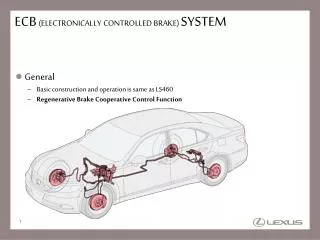

ECB (ELECTRONICALLY CONTROLLED BRAKE) SYSTEM
E N D
Presentation Transcript
ECB(ELECTRONICALLY CONTROLLED BRAKE) SYSTEM • General • Basic construction and operation is same as LS460 • Regenerative Brake Cooperative Control Function
ACTIVE STABILIZER SUSPENSION SYSTEM • Overall • Enhanced cornering ability to decrease an amount of roll by controlling twist of the front / rear stabilizer bars for the vehicle posture control during cornering To decrease rolling angle during cornering To change steering characteristic by driving conditions : Stabilizer bar effect : Active stabilizer suspensionsystem effect
ACTIVE STABILIZER SUSPENSION SYSTEM HV Battery Unit DC/DC Converter for EPS and Active stabilizer • Main Components Air Suspension ECU Rear Active Stabilizer ECU Steering Control ECU Rear Active Stabilizer Actuator Skid Control ECU Front Active Stabilizer Actuator Damping Mode Select Switch Front Active Stabilizer ECU
ACTIVE STABILIZER SUSPENSION SYSTEM • Major Difference from GS450h
DLC3 ACTIVE STABILIZER SUSPENSION SYSTEM Steering Angle Sensor Yaw Rate Sensor Steering Control ECU Suspension Control ECU Deceleration Sensor • System Diagram AC 46 V AC 46 V Front Active Stabilizer Actuator Rear Active Stabilizer Actuator Front Active Stabilizer Control ECU Rear Active Stabilizer Control ECU Motor Motor Motor Rotation Sensor Motor Rotation Sensor DC 46 V DC/DC Converter[EPS /Active Stabilizer Suspension] Damping Mode Select Switch Speed Sensors DC 288 V Center Console Switch Module HV Battery Skid Control ECU Driver Side Switch Module Main Body ECU Meter ECU • Multi-information Display • Master Warning Light • Buzzer
Vehicle Roll Angle Lateral Acceleration ACTIVE STABILIZER SUSPENSION SYSTEM • Vehicle Roll Angle • Amount of twisting the stabilizer bar are controlled based on signals of actual turning angle of tire, vehicle speed, lateral acceleration, and AVS mode • OPERATING CONDITIONS • Shift position except “R” and “N” range • Vehicle speed is satisfied following condition CHARACTERISTIC OF ROLL ANGLE ON OFF 5 km/h (3.2 mph) 20 km/h (12.5 mph) Vehicle Speed : with System : without System
ACTIVE STABILIZER SUSPENSION SYSTEM • Active Stabilizer Actuator • Each stabilizer bar position is kept to the neutral position by the vehicle’s weight, when system is OFF Each stabilizer bar position is not fixed, however is not free
ACTIVE STABILIZER SUSPENSION SYSTEM • Warning Message • System condition check by multi-information display
SERVICE POINT (ACTIVE STABILIZER SUSPENSION SYSTEM) • Active Test • In active test mode, each active stabilizer control ECU operates each active stabilizer actuator automatically.
SERVICE POINT (ACTIVE STABILIZER SUSPENSION SYSTEM) • Active Test • If Active Test does not operate, test mode DTCs are output
SERVICE POINT (ACTIVE STABILIZER SUSPENSION SYSTEM) • Initialization and Calibration Items • After disconnecting auxiliary battery
STEERING • Overall • Vehicle speed sensing type EPS system and VGRS system are used for all models as STD
DLC3 STEERING Steering GearUnit Rotation Angle Sensor EPS Motor Torque Sensor Lock Solenoid • System Diagram VGRS Actuator Motor AC33 – 46 V Rotation Angle Sensor Steering Control ECU Power Steering ECU Parking Assist ECU DC 33 – 46 V DC/DC Converter[EPS /Active Stabilizer Suspension] HV ECU Combination Meter DC 12 V DC 288 V Auxiliary Battery HV Battery Skid Control ECU Suspension Control ECU Speed Sensors Steering Angle Sensor Yaw Rate Sensor Driving Support ECU Deceleration Sensor
STEERING • Layout of Main Components HV Battery Unit DC/DC Converter for EPS and Active stabilizer Parking Assist ECU Air Suspension ECU Auxiliary Battery Steering Control ECU Power Steering ECU Driving Support ECU Skid Control ECU HV ECU • Steering Gear Unit • Torque Sensor • EPS Motor • Rotation Angle Sensor • VGRS Actuator • Motor • Rotation Angle Sensor • Lock Solenoid
AC 46 V STEERING • DC/DC Converter for EPS and Active Stabilizer • Usually, DC/DC converter steps down the HV battery voltage from DC 288 V to DC 46 V and supplies electrical power to the power steering ECU. EPS Motor High-voltage use permission signal DC/DC CONVERTER[EPS /Active Stabilizer Suspension] HV ECU Power Steering ECU DC 288 V Step Down Circuit HV Battery Shut Down Circuit Boost Converter Circuit To Fr/Rr Active Stabilizer ECU DC 12V Auxiliary Battery Boost Circuit
AC 46 V AC 33 V STEERING • DC/DC Converter for EPS and Active Stabilizer • When there are any HV battery voltage problems, the DC/DC converter temporarily converts the auxiliary battery voltage from DC 12 V to approx. DC 33 V and supplies electrical power to the power steering ECU. EPS Motor High-voltage use permission signal DC/DC CONVERTER[EPS /Active Stabilizer Suspension] HV ECU Power Steering ECU DC 288 V Step Down Circuit HV Battery Shut Down Circuit Boost Converter Circuit To Fr/Rr Active Stabilizer ECU DC 12V Auxiliary Battery Boost Circuit
SERVICE POINT (STEERING) • Initialization and Calibration for Steering System *: Straight-ahead judgment conditions are required
Front ACTIVE STABILIZER SUSPENSION SYSTEM • Active Stabilizer Actuator • DC brushless motor and reduction gear twist stabilizer bar on both sides NOTE:Active stabilizer actuator is non-disassemble parts Stator Coil Rotor Gear Reduction Mechanism(Strain Wave Gearing Mechanism) Front Stabilizer Bar (LH) Front Stabilizer Bar (RH) Brushless Motor Motor Rotation Sensor (3 Hall ICs)
ACTIVE STABILIZER SUSPENSION SYSTEM • Active Stabilizer Actuator • Reduction mechanism • Both stabilizer bar shifts 2 teeth per wave generation 1 rotation 402 teeth Front Stabilizer Bar (RH) Front Stabilizer Bar (LH) 400 teeth Wave Generator Flexible Gear Circular Gear Rotor Gear Gear Ratio : 1/200
REFERENCE (ACTIVE STABILIZER SUSPENSION SYSTEM) • Reduction Mechanism • Construction Stator Gear Flexible Gear Wave Generator Ball Bearing is between flexible gear and wave generator Meshing NOTE:Indicate this is the reduction mechanism as VGRS system for GS430 example View from stator gear side (Steering wheel side) Not meshing
REFERENCE (ACTIVE STABILIZER SUSPENSION SYSTEM) • Reduction Mechanism • Operation of strain wave gearing Motor Shaft Flexible Gear (100 teeth) Wave Generator Ball Bearing (Between flexible gear and wave generator) Stator Gear (102 teeth) View from stator gear side (Steering wheel side)
REFERENCE (ACTIVE STABILIZER SUSPENSION SYSTEM) • Reduction Mechanism • Operation of strain wave gearing Stator gear fixed View from stator gear side (Steering wheel side)
STEERING • VGRS Actuator • VGRS actuator is relocated and spiral cable is discontinued Input Strain Wave Gearing Output Motor Lock Mechanism Torque Sensor (for EPS) Torsion Bar Pinion Shaft
STEERING • VGRS Actuator • Strain wave gearing [ ]: Number of teeth Stator Gear [102] Driven Gear [100] LS460 GS430 Flexible Gear [100]