Disc Brake Operating Principles
120 likes | 160 Views
This informative guide delves into the operation and components of disc brake systems, including the rotor, caliper, and brake pads. Learn about the differences between front-wheel-drive and rear-wheel-drive vehicles, as well as the importance of servicing bearing assemblies. Discover how fixed and floating calipers work, and the significance of heat dissipation in maintaining brake performance. Gain insights into the hydraulic pressure systems that operate disc brakes, and the implications of piston design on brake function.

Disc Brake Operating Principles
E N D
Presentation Transcript
Disc brake components • • The rotor • In disc brake systems, the rotor is an iron or steel disc that revolves with the wheel. In most vehicles, the wheel is bolted to the rotor. Brake pads are applied to both sides of the rotor to create friction, which in turn converts kinetic energy into heat and dissipates it.
Disc brake components • • In front-wheel-drive vehicles, the drive train drives the rotors on the front wheels. In such cases, the rotor is either splined to the drive axle or connected to it in some other way. • • In rear-wheel-drive vehicles, the rotor often includes the hub and bearings, which support the wheel itself. • • In some cases, the rotor on either a front-wheel-drive or rear-wheel-drive vehicle may be a separate unit. If so, the same bolts that hold the wheel fasten the rotor to the hub.
Disc brake components • Because disc brakes can clean and cool themselves, they are generally considered to be more effective than drum brakes. • Bearing assemblies support the rotor while allowing it to rotate. Each bearing needs servicing at the same time as the rotor. These bearings differ depending on the make of the vehicle and the type of drive line it uses (front- or rear-wheel). • NOTE: In order to remove the rotor, it is necessary to remove the wheel and caliper.
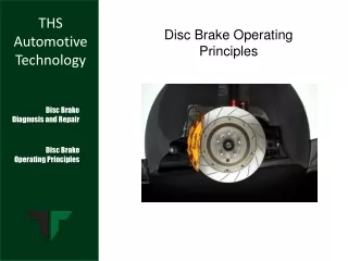
Disc brake components • • The caliper • During brake applications, the caliper applies brake pads to both sides of the rotor, in effect squeezing the rotor. • Disc brake systems use either a fixed or a floating caliper design. Disc brake caliper and pads
Disc brake components • NOTE: Brake systems must dissipate tremendous amounts of heat or the brakes will fail. Because of their exposure to the surrounding air, disc brakes dissipate heat more quickly than drum brakes. Some rotors are ventilated, allowing air to circulate between the friction surfaces and dissipate heat even more efficiently. • NOTE: Calipers do not use any brake return springs. Seal deflection releases the brake pads.
Disc brake components • When the driver releases the brake pedal, the piston seal pulls back the piston, allowing for brake release.
Operation of fixed caliper disc brakes • • When the driver depresses the brake pedal, hydraulic pressure from the master cylinder enters the caliper and then travels through transfer passages to the pistons. Transfer passages are either internally drilled passages or externally mounted tubing. • There is an equal number of pistons on each side of the rotor. • All pistons receive fluid pressure simultaneously. In turn, the pistons apply pressure to the brake pads.
Operation of fixed caliper disc brakes • • Fixed calipers usually have four pistons—two on each side of the rotor. • • The fixed caliper does not move when the driver applies the brake. The fixed caliper (and sometimes a dust shield) are mounted directly on the anchor plate or adapter. • • In some vehicles, shims and spacers between the caliper and anchor plate or adapter allow for adjustment. In these vehicles, it is important to center the caliper on the rotor precisely. To successfully center the caliper, place the shims between the caliper and anchoring device. • • Fixed caliper systems have one significant disadvantage over floating caliper systems: if one of the pistons becomes stuck in its bore, the other three still apply pressure to the rotor. Pressure from only three pistons can cause the pads to wear unevenly, resulting in damage to both the rotor and the caliper. Operation of fixed caliper disc brakes
Operation of floating caliper disc brakes • • In the floating caliper design, the caliper moves laterally when the driver applies the brakes. The caliper does not rotate with the wheel, however. The floating caliper uses only one piston, which is located on the caliper’s inward side. • In some vehicles, bolts hold the floating caliper to the brake assembly. The bolts are actually threaded pins upon which the caliper can slide.
Operation of floating caliper disc brakes • In other vehicles, spring plates retain the caliper by matching grooves in the adapter/connecting plate and the caliper. Bolts or retaining pins can hold these plates. • NOTE: Before attempting repairs, determine whether the system uses a floating or fixed caliper. If the caliper has one piston, it is floating; if it has two or more, it is fixed.
Operation of floating caliper disc brakes • • When the driver depresses the brake pedal, hydraulic pressure from the master cylinder is applied to a single piston on the inboard side of the caliper. This piston forces the inboard pad against the rotor. • • As the inboard pad contacts the rotor, the caliper forces inward, thus bringing the outboard pad in contact with the rotor. • NOTE: The floating caliper centers itself on the disc. • • When the driver releases the brake pedal, the piston seal pulls the piston back, allowing for brake release. • NOTE: Disc brake systems do not use return springs to release the pads.