Download
1 / 27
270 likes | 509 Views
ITS - FWD - beam pipe installation. RB24 side. RB26 side. beam pipe Central Section. T0 L. V0 L. SPD. SDD. SSD. T0 R. V0 R. FMD-Si3. Front Absorber. RF valve. PMD. FMD-Si2. FMD-Si1. Elements considered

E N D
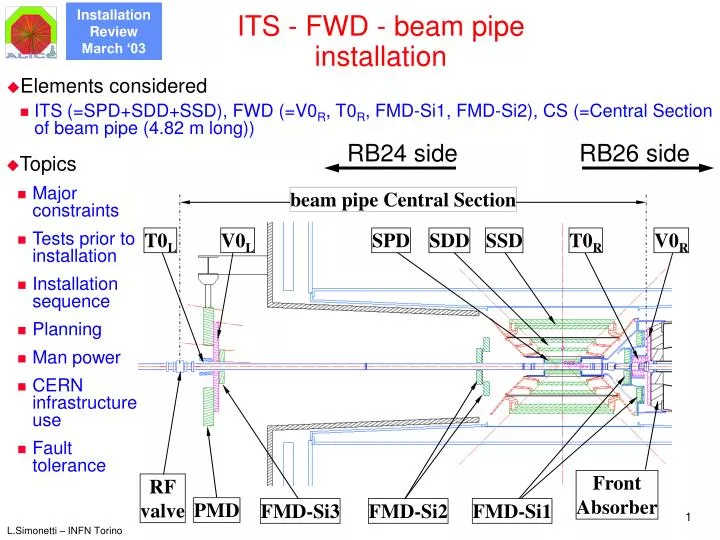
ITS - FWD - beam pipe installation RB24 side RB26 side beam pipe Central Section T0L V0L SPD SDD SSD T0R V0R FMD-Si3 FrontAbsorber RFvalve PMD FMD-Si2 FMD-Si1 • Elements considered • ITS (=SPD+SDD+SSD), FWD (=V0R, T0R, FMD-Si1, FMD-Si2), CS (=Central Section of beam pipe (4.82 m long)) • Topics • Major constraints • Tests prior to installation • Installation sequence • Planning • Man power • CERN infrastructure use • Fault tolerance
ITS - FWD - beam pipe installation • Major constraints • Presence of m-absorber on RB26 side: forces asymmetric installation • Small clearance SPD – CS-pipe (5 mm): forces specific assembly of SPD (no SPD sliding over beam pipe) • Minimum material budget: all services have to be connected at both ITS ends • Consequences • Complex and rather long installation procedure • Several installation approaches have been studied during three years. The present solution is being pursued by: • testing the details on a full-scale installation mock-up • regular discussions within ALICE and with the beam pipe group • AT/VAC has the responsibility of all the operations on the pipe and on its support and bakeout shell
Pre-installation and functional tests • Tests prior to installation • Mechanical • With the installation mock-up • With the final ITS+FWD+pipe mechanics and tools, with the actual detectors weights, and with the real TPC: final test in SLX2 between July and December 2004 • Space requirement : a ~6-8 m long area corresponding to the RB24 side for the (dummy) beam pipe installation • Tools requirements: dummy beam pipe with accessories (bellows, flanges, valve); dummy front absorber • Electrical / electronics / cooling • Individual sub-detectors test upon arrival at CERN • ITS re-tests will be performed in the Si-lab in Meyrin (build. 186) with individual sub-detectors and with SPD+SDD+SSD assembled together (final effectiveness test of grounding scheme and of sub-detectors EM screens) • Space requirement : for the detectors (4x4 m2 for each SPD, SDD, SSD); for the the racks (power supplies, cooling, DCS, shoe-boxes); for the computing (2 workstations per detector); in total about 75 m2
Installation step 1. (6 days) (all durations assuming 1 shift / day) Frontabsorber IP TPC/C3 TPC/C2 4.5 m jaws TPC/C4 ITS rails L3 TPC/C1 • Assumptions before starting ITS installation: • The beam pipe in the Front Absorber (RB26) is already leak-tested and refilled with N2; its flange is available at the nominal coordinates out of the Front Absorber • The TPC is at 4.5 m from the int. point (IP) on the RB24 side (opposite to the absorber) • The 4 fixation plates (C1…C4) of the ITS rails on the TPC are pre-assembled so that they will become aligned when the ITS will be coaxial with the TPC at the end of the installation. • First installation step • Install and align (survey) the ITS rails so that they are 1 mm below the nominal beam axis (to minimize the displacement of beam-pipe bellows while linking ITS to TPC) • On the absorber: rails held by remotely actionable jaws
Installation step 1. Rails for ITS services Rail for ITS C4 Rail for beam pipe C1 C2 C3 C4 C3
Installation step 2. (a) (13 days) • slide ITS through the TPC • Responsibility ALICE • Slide up to 1.56 m from the IP (place for FWD & SPD) IP • Install beam pipe on ITS rails • Responsibility AT/VAC • 5 m long temporary support needed on RB24 side • Align beam pipe with rails 1.56 m • Slide beam pipe to absorber • Responsibility AT/VAC • Survey beam pipe • Connect to absorber flange • Bakeout and leak test (9 days) • Refill with clean gas (N2) • Install outer ITS (=SDD+SSD) on rails • Crane lowers ITS underground; align it to the rails (and/or external references),
Installation step 2. (b) Section 1 Section 2 Beam pipe Section 3 Section 4 Beam pipe support RF valve RF valve support CMS experiment bakeout shell beam pipe linked to front absorber flange The 4 sections of the support and bakeout shell supports and protects the beam pipe Central Section (Be) during the different installation steps adjustment tools to compensate sagging
Installation step 2. (c) Section 1 Section 2 Section 1 Section 2 Beam pipe Section 3 Section 4 Beam pipe support RF valve RF valve support
Installation step 3. (4 days) 45º 45º T0 Section 1 • Install V0 and T0 on RB26 • Responsibility ALICE • Each half V0 and half T0 are pre-assembled together to save time during installation in pit. • V0 and T0 are fixed to the absorber V0 • Cabling and test of V0 & T0 beam pipe bellows V0 T0 SSD SDD T0 TPC/C4 V0 • Remove section 1 of beam pipe support • Responsibility AT/VAC
Installation step 4. (3 days) B A A • Install temporary support • It’s made of 2 halves; the upper one is brought into position through rotation about axis “A” (to avoid risks for the beam pipe) • It has 4 flaps (“B”) at ±45º for fixation of beam-pipe and SPD supports prior to transfer their load to ITS • Align (survey) temporary support to the beam pipe
Installation step 5. (4 days) • Spoke structure reduces material in front of FMDs and allows for visual inspection • Test FMDs • FMDs have pigtails up to the outer edge of the 3rd cone • Remove 3rd cone lifting tools FMD – Si1 Dummy 3rd cone • Fix support for beam pipe and FMD (“3rd cone”) to temporary support • The 3rd cone is made of two halves containing the FMDs • lifting tools allow for slow and accurate positioning of 3rd cone Lifting tool
Installation step 6. (2 days) • Mount and adjust monitoring system of bellow movements • Responsibility ALICE • Non-touching capacitive sensors are proposed • Mount and adjust 1st support to the beam pipe • Responsibility AT/VAC • Survey Lifting tool
Installation step 7. (8 days) Temporary support 3rd cone SPD services Section 2 SPD cone • Install the two SPD half-cylinders (Resp. ALICE) • Two half cylinder/cones • Specific installation tools are being designed • SPD services (cables, fibres & capillaries) are pre-assembled in the cones • Fix the two, coupled, SPD half-cylinders to temp. support, above the 3rd cone, using a 2nd series of bolts & precision plugs • SPD fixed in cantilever mode to temp. support, SPD pigtails on RB24 side unconnected • Remove section 2 of beam pipe support (Resp. AT/VAC)
Installation step 8. (7 days) Temp.Support • Mount and adjust 2nd support to the beam pipe (resp. AT/VAC) • Survey • Outer ITS, SPD & beam pipe are now an integral unit SPD SDD SSD TPC/C4 • Slide outer ITS onto SPDs (Responsibility ALICE) • Transfer load of SPD and 3rd cone (beam pipe) from temporary support to ITS • Connect SDD and SSD on RB26 side • Final fixation of SPD pigtails on RB24 side to ITS cone
Installation step 9. (3 days) • Remove section 3 of beam pipe support (Resp. AT/VAC) • Install FMD-Si2 • Also FMD-Si2 detector rings are made of top and bottom halves • The dedicated support structure is being designed, to fix FMD-Si2 to ITS • The temporary support used on the RB24 side can also be used on the RB26 one for the installation of FMD-Si2 FMD detector Section 3 FMD-Si2
Installation step 10. (7 days) TPC Service Supp. Wheel ITS-TPC links devices • Assemble the two half-cylinders of composite material, having the ITS services on them • Slide them through TPC while monitoring beam pipe bellows on RB24 • connect ITS & FMD-Si2 services at the patch panels Patch panels for ITS and FMD-Si2 CS beam pipe with its chariot • Install chariot for ITS services on RB24 TPC Service Supp. Wheels CS beam pipe with its chariot Patch panels for ITS and FMD-Si2 ITS service chariot
Installation step 11. (0.5 days) ITS lift tool ITS Remote control tools to operate the ITS lift tools on both rails in parallel ITS –TPC link device TPC ITS • Lift ITS by 3 mm to prepare for TPC sliding to interaction point (using a contact sensor and viewed by camera during operation)
Installation step 12. (3 days) TPC ServiceSupport Weels • Slide TPC over ITS to interaction point • Simulation of the TPC sliding showed that vertical displacements are expected during this operation • Constant monitoring of the TPC absolute alignment and of the displacement of the beam pipe bellows on RB26 is required • Lifting tools are foreseen in the TPC to re-align TPC position to the nominal beam axis (see T.Meyer talk) TPC Service Supp. Wheels Removal of C4 link point between TPC and ITS rails when TPC reaches the Front Abs. CS beam pipe with its chariot TPC/C4removed TPC SSW TPC/C3 TPC/C2 TPC/C1 Patch panels for ITS and FMD-Si2 TPC/C4 ITS service chariot ITS
Installation step 13. (0.5 days) ITS –TPC link device connected on both TPC sides (top) TPC ITS • Link ITS to TPC, so that TPC, ITS and CS beam pipe become an integral unit • ITS is appended to TPC from its top; end-position of TPC sliding is detected by appropriate electrical contacts • ITS is lowered to the nominal position, i.e. one mm higher than the rails • a plug at ITS bottom on RB24 side blocks ITS angular movements • The link-devices allow for galvanic insulation of TPC from ITS
Installation step 14. (6 days) • Remove section 4 of beam pipe support and bakeout shell • Mount and adjust 3rd support to the beam pipe (Resp. AT/VAC) • The support is connected to TPC • Survey needed ITS servicechariot • Remove beam pipe chariot TPC service wheel • Bend ITS+FWD services and temporarily fix them to TPC service wheel ; remove terminal half-cylinders of service chariot (not shown) (Responsibility ALICE)
Installation step 15. (5 days) • Free ITS rails on front abs. • by opening the remotely controllable jaws • Remove ITS rails • Lift ITS-service chariot from the ITS rails • Mount conical sections to the ITS-service chariot (to preserve PMD acceptance) and chariot lifting tools • Hang ITS-service chariot to the TPC Service Support Wheels (SSW) on RB24 Chariot lifting tools Conicalsections
Summary of installation schedule • In the present planning the ITS – FWD – beam-pipe installation starts on middle June 2006 • Assuming one shift per day, and without parallelization of tasks, the present estimate indicates a overall duration of 15 weeks.
Commissioning • All the concerned detectors and sub-systems (power, cooling, monitoring) will be thoroughly tested during the construction phase • After the construction, the ITS barrels will be operated for final debugging for about 4-8 weeks • ITS and FWD commissioning (sub-systems included) has to be performed during the installation: no time to re-open the detectors for reparations. • After FWD installation and after ITS installation, tests with pulser will be performed • The ITS will be tested after the RB24 service chariot has been slid to the final position (turn-on requires the cooling system to be functional) • Some monitoring of individual subdetectors is possible during installation (e.g. during nights), to ensure regular operation, without increasing the already long installation time. The appropriate temporary connections are currently under study • Any intervention to the FEE and the detectors is excluded
Survey and alignment • Survey of the working position • See installation sequence before • For all the sub-detectors: whenever the positioning capability of the installation tools cannot guarantee the knowledge of the detector positions within ± 0.1 mm (Still to be defined ) • Monitoring during the installation and operation • Monitor of the beam pipe bellows on the RB26 side : continuously since the installation of the 1st CS beam pipe support • Monitor of the clearance SPD – beam-pipe : continuously since the installation of the half-cylinders • Monitor of the TPC absolute position: continuously since its sliding-in to the interaction point • Monitor of the ITS-TPC relative position: continuously since the arrival of the TPC on the interaction point
Maintenance and access in the future • Accessibility of the various elements • All the considered detectors can be accessed only after the removal of the TPC (operation which implies several weeks) • Time estimates for various exchanges/repair of critical elements • Careful intervention ITS / Forward detectors during shutdown 3 months would allow sufficient time for major repair operation • Access for bake-out - Alice detector fully operational 5 to 6 weeks (depends on the extent of commissioning) • Fast access for bake-out - Alice detector not operational 2 to 3 weeks possibly even faster • Fault tolerance • ITS sub-detectors are rather highly segmented for both the power supplies and the cooling system (each segment corresponds to few% of the acceptance), so in case of fault leading to shutdown of one element the loss in acceptance would be tolerable • FMDs, particularly the FMD-Si1, will embody as much redundancy as possible. • All the sub-detectors have spare parts ranging from 10% to 20% • The monitoring tools installed within the TPC body will have redundancy.
Personnel and resources • Personnel from the ALICE Institutes will be present during the pre-installation mechanical test (about 13 weeks for installation and 8 weeks for removal, from 7/2004) for the movements of the sub-detectors, their connections (cabling, cooling), etc. • Additional personnel from the ALICE Institutes will be present during the installation (about 15 weeks from 6/2006) for the functional tests & commissioning. • Personnel from the ALICE DCS, DAQ and trigger groups is needed during the installation for the first setup of the detector DAQ/trigger branches and then on-call • Personnel for the external cooling systems (ST/CV) is needed for the first setup of the detector cooling control system and then on-call
CERN infrastructure use • Road Transport • In principle ITS needs only one transport, at the start of installation, from the Si-Lab in Meyrin (build.186) to SLX2 : • on a vibration-free vehicle for the barrel • On standard CERN transportation trucks for the several racks (power supply, cooling, etc.) • The total weight of the ITS barrel is about 100 kg • Cranes usage and survey • CERN personnel for the survey and the crane operation is needed on the basis of a detailed schedule that has to be prepared; • Present very preliminary estimates for the survey indicate a need for 20% of the time both during the pre-installation mechanical test (13 weeks from 7/2004) and during the installation (15 weeks from 6/2006). • Need of the crane should be limited to few days during the same period