Download

1 / 36
360 likes | 433 Views
Explore the design and implementation of a high-accuracy AC voltage reference using digital waveform generation. Learn about the circuit, software, and improvements in performance. Achieve high calibration accuracy suitable for modern digital multimeters.

E N D
The Design of a Calculable AC voltage reference using digital waveform generation NCSLI 2013, Nashville
The design of an AC voltage reference source using a digital to analogue converter controlled by a microcontroller to produce a calculable RMS AC voltage reference with accuracy suitable for calibrating high performance Digital multimeters. Abstract NCSLI 2013, Nashville
To provide a method for secondary and below laboratories with the ability to generate high accuracy AC Voltages • Investigate errors associated with digitally generated AC Voltages, as well as the practical application of digitally generated waveforms in commercial calibration Technical Objectives NCSLI 2013, Nashville
To investigate alternatives to traditional AC voltage verification methods • To enhance calibration laboratories understanding of verification of high performance modern DMM’s Learning Objectives NCSLI 2013, Nashville
The Requirement The calibration of Today’s Modern high performance Digital Meters which offer ACV Accuracy in the order of 80-100 ppmTo achieve a stand off ratio of just 4 to 1requires an accuracy of around 20 ppm. This is not possible with a multi-product calibrator NCSLI 2013, Nashville
The Solutions 1) Multi–Junction Thermal Transfer Standard 2) Calculable AC voltage reference NCSLI 2013, Nashville
The Solutions : Multi-Junction Thermal Transfer Standard NCSLI 2013, Nashville
The Solutions : Calculable AC Voltage Reference NCSLI 2013, Nashville
The Concept of theCalculable waveform Digitally create an AC waveform using a digital to analogue (DAC) converter. In our experiments we chose a waveform based on 256 steps. Single step the waveform to allow the level of each step to be measured as a DC level. NCSLI 2013, Nashville
The Concept of theCalculable waveform The RMS value of the waveform is then calculated using the following formula Where :Vrms = RMS Ac voltage output V = measured DC voltage of ‘step’ n = number of steps NCSLI 2013, Nashville
History This is not a new idea. This technique was pioneered as long ago as 1988 where results against Thermal converters gave uncertainties at the 7 volt level of just 5ppm. NCSLI 2013, Nashville
What has changed There is now a much greater need for high accuracy ACV. In 1988 we were only seeing the first developments in High accuracy AC DMM’s. Now almost every laboratory has a high performance DMM NCSLI 2013, Nashville
What has changed Digital Electronics along with the rapid development of digital to analogue converters for high quality audio has now made it much easier to implement this concept. NCSLI 2013, Nashville
The Circuit Clock 10V Reference Input The design uses a PIC micro controller, programmed with the waveform to directly drive a DAC. The PIC is directly controlled from an RS232 interface. Control Interface Micro ControllerPIC 16F84 DAC AC Voltage Output NCSLI 2013, Nashville
The DC Reference The D to A converter needs a short term stable 10Volt DC reference. The Linear Technology LTZ100 reference can easily provide better than 1ppm stability over the short term 2/3 hours required. As the LTZ1000 is temperature stabilised temperature variations over the measurement period will not add any significant contributions to an uncertainty budget NCSLI 2013, Nashville
Improvements Vs Performance The circuit used is extremely simple. Early design’s used two converters, with the output being switched between them to remove glitches. With modern converters this is not necessary. The PIC micro controller directly drives the converter, loading the code into the converter directly from it’s memory, also clocking the converter after each data load. This very simple approach requires some machine code for the PIC to make it run as fast as possible. All timing comes from the crystal oscillator driving the PIC. NCSLI 2013, Nashville
The Software The AC reference is very simple to control, with just a few commands needed. 1 - 15Hz 2 - 60Hz 3 - 200Hz 4 - 1000Hz S - Stop waveform and set to zero X - Advance 1 step Y - Advance 10 steps Z - Advance 64 steps NCSLI 2013, Nashville
Taking the DCV Measurements The DCV measurements can be taken with a high performance 8 digit DMM. This will typically give full scale & linearity uncertainties of less than 5ppm. As there are over 256 measurements to be made it is recommend that the process be automated by using a PC & software. NCSLI 2013, Nashville
Measuring Software A procedure to measure each step was written using Procal. As each step is measured it is squared and added to a running total. The procedure being 256 steps long, takes about 40 minutes to run automatically. Although the measurement procedure could be written in any language Procal has the advantage to work with any DMM without changing code. NCSLI 2013, Nashville
Basic Measurement Diagram NCSLI 2013, Nashville
Practical Set up NCSLI 2013, Nashville
Voltage Range With a 10V input the peak output of the converter will be 10Volts; giving an RMS voltage of 7.07V To get a 1V output the 10Volt output can be resistively divided down allowing the output to still be single stepped and measured on DC. Note an IVD cannot be used to divide down the DC output. However it can be used on the AC output NCSLI 2013, Nashville
This error is most difficult to evaluate.It is dependent on the DAC used. The DAC we have chosen is typically used for audio will be very ‘clean’. The approach used by Transmille has been to look at an individual step on a scope and estimate an error based on the size and duration of the transitions. Errors Switching Glitches and transition NCSLI 2013, Nashville
Errors Switching Glitches and transition Typical figures for this, at a frequency of 50Hz, where there is a step every 80uS, worst case measurements give glitch times of around 8nS, with a glitch size of around 10% of the step. This gives transition errors around the 10ppm level. In practice as some glitches will add and some will subtract the real error will be much less. NCSLI 2013, Nashville
Rise and Fall time Providing the rise and fall times are equal they do not contribute to errors. The error caused by a difference in rise/fall times can be mathematically calculated DC offsets Any DC offsets in the DAC will be measured and added to the calculated RMS figure. However if the device being calibrated is AC coupled DC offsets in the AC output will give an error and it may be best to trim any offsets out to avoid this problem. Errors from Rise / fall times & DC offsets NCSLI 2013, Nashville
Errors from Loading effects Output Loading When measuring the output with a thermal converter the load effect on the 2 wire output will need to be considered.When using measuring the output with a typical DMM loading effects will be negligible NCSLI 2013, Nashville
Errors from drift in DC Reference Source & DAC As the AC source is a transfer device it is only the short term drift between the DC measurement of the system and the subsequent use on AC that contributes to the error. Long term changes in the reference or the DAC linearity or gain do not contribute as the system is calibrated before use. NCSLI 2013, Nashville
Uncertainties Typical laboratory figures for uncertainty Imported DC Voltage Measurement 5ppm Resolution of DC voltage Measurement 0.1ppm Switching transition errors 10ppm Short term stability of DC reference and DAC* 2ppm Combining for 95% (K=2) gives 13ppm * Includes effects of temperature for +/- 2’C from Tcal NCSLI 2013, Nashville
Verifying the accuracy Measurements made by Transmille Transmille best AC measurement capability uses our Fluke 540b thermal transfer, the accuracy of this Instrument is enhanced by measuring the output of the thermal converter directly. Loading effects on both AC and DC measurements were compensated for. Tests performed against a Wavetek 4920, Transmille 8081, Agilent 3458A and Fluke 8508A provided similar results. Typical readings obtained Single step calculation = 7.055681 Measurement by thermal Transfer 540B = 7.055779 Error = 14 ppm NCSLI 2013, Nashville
Frequency Range To date Transmille’s interest has been In the frequency range 40Hz to 1kHz. The design could generate frequencies below 1Hz with no additional errors. Frequencies up to 10kHz could also be generated with increased error from switching. NCSLI 2013, Nashville
Improvements…… Extending the Voltage range. A simple resistive divider to provide 1V and 100mV outputs. A DC voltage amplifier to provide a 100V output. Both could be again ‘calibrated’ at DC using a known DMM to provide the calculated AC RMS value NCSLI 2013, Nashville
Other Functions…… Non sine wave outputs With this method it would be very easy to generate other wave shapes to evaluate performance of converters including crest factor. NCSLI 2013, Nashville
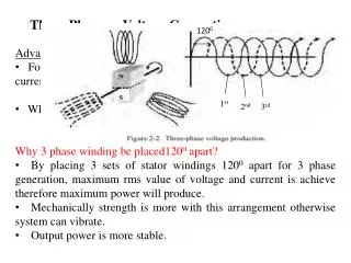
Power and Phase….. Future development of this technique could be to add additional converters to allow for several outputs. Up to 6 outputs could easily be provided for 3 phase simulation of power, with an accurate phase, or delay between the outputs. If all the outputs were at the same 7V level this would provide a very affordable solution for a phase and power reference. NCSLI 2013, Nashville
References [1] R. Kinard, and L. A. Harris “ A digitally synthesized sine wave source with +/- 1 ppm amplitude stability. “ in Euromeas ’77 Conf Digest. Institute Elect. Eng. Conf. Pub no 152, Sept. 1977 [2] Oldham N., Hetrick P., Zeng X., “A Calculable, Transportable Audio Frequency AC Reference Standard”. IEEE Transactions on I & M, April 1989, Vol. 38. [3] Oldham N., Bruce W., FU C., Cohee A., Smith A., “An Intercomparison of AC Voltage Using A Digitally Synthesized Source”. IEEE Transactions on I & M Vol. 39 No. 1, February 1990 NCSLI 2013, Nashville
Conclusions Digital synthesized waveforms can provide a low cost and easy to use solution for DC to AC voltage transfer. Copies of our paper and presentation are available on our booth on USB memory sticks NCSLI 2013, Nashville