4 . EMC measurement methods
4 . EMC measurement methods. EMC measurement methods. Why EMC standard measurement methods. Check EMC compliance of ICs, equipments and systems Comparison of EMC performances between different products, different technologies, designs, PCB routings

4 . EMC measurement methods
E N D
Presentation Transcript
EMC measurement methods Why EMC standard measurement methods • Check EMC compliance of ICs, equipments and systems • Comparison of EMC performances between different products, different technologies, designs, PCB routings • Improve interaction between customers and providers (same protocols, same set-up)
Control - Acquisition Radiated or conducted coupling Acquisition system 50Ω adapted path Device under test Coupling device • Spectrum analyzer • EMI receiver • Oscilloscope • Coupling network • Antennas • Wave guide Emission requirements verified ? Emission measurement methods Emission – General measurement set-up
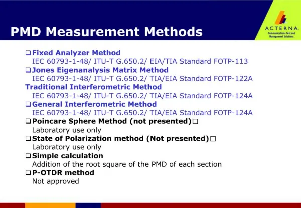
Emission measurement methods International standards for IC emission measurement methods
Emission measurement methods GTEM cell : radiated emission up to 18 GHz Emission spectrum
IC Complex implementation with multiple power pins 1ohm Emission measurement methods IEC 61967-4 International Standard : 1/150 Ohm method Spectrum Analyser
Y axis dBµV X axis freq 32MHz Emission measurement methods IEC 61967-3 International Standard : Near field scan Microcontroller - 32 MHz scan High Low
A A E P MI EE T T MS- C W BUS 1K D D CAN T M MSI 1 0 Hx Probe Power rails 28K 32K FEEPROM FEEPROM Priviledged current measurement Power rails K IN MMI BDM W T RAM U CPU 12 LIM D60 2K W CGM C BKP MEBI R Emission measurement methods IEC 61967-3 International Standard : Silicon scan
Failure detection Injected level Extraction Disturbance generation Radiated or conducted coupling 50Ω adapted path Device under test Coupling device • Coupling network • Antennas • Wave guide • Harmonic signal • Transients • Burst Immunity requirements verified ? Immunity measurement methods Immunity – General measurement set-up
Immunity measurement methods International standards for IC susceptibility measurement methods
Signal generator Oscilloscope Good signal Coupling Capacitance or Failure signal IEEE Bus 10W Amplifier DUT Power increase loop until failure PC Monitoring Frequency loop 1 MHz – 3 GHz Immunity measurement methods IEC 62132-3 International Standard : Direct Power Injection Device under test Dout Printed Circuit Board
DUT Immunity measurement methods IEC 62132-2 International Standard : Bulk Current Injection Parasitic current Fault CAN Bus Normal current Microcontroler Measured current RF power • Inductive coupling to the network • Parasitic current injected on the chip • Limited to 1 GHz
Spectrum analyzer 40 GHz (40 K€) Amplifier 3 GHz 100W (60 K€) Vector Network Analyzer 10 GHz (100 K€) Signal Synthesizer 6 GHz (20 K€) GTEM cell 18 GHz (15 K€) EMC equipments • Expensive …. • Complete EMC laboratory : 500 K€
Models – What for ? IC designers want to predict EMC prior fabrication Noise margin Voltage bounce on Vdd • IC designers want to predict power integrity and EMI during design cycle to avoid redesign • EMC models and prediction tools have to be integrated to their design flows
Models – What for ? Equipment designers want to predict EMC before fabrication © Siemens Automotive Toulouse • Most of the time, EMC measurements are performed once the equipment is built. • No improvements can be done at conception phase. • Predict EMC performances IC, board, equipment optimizations
101 dipoles Dipoles 101 R,L,C,I ICEM 102 R,L,C,I LEECS 104 R,L,C,I Expo PowerSI EMC of IC models EMC Models depends on the targeted complexity and the confidentiality. Level 100 V(f), 100 Z(f) Equipment V, Z Board Component Physical 106 R,L,C,I spice Complexity low medium high x-high Confidentiality