Methodology for Tracking Downstream End of CC-1 with ASTRA and Dark Current Measurements
This document outlines the methodology for tracking the downstream end of CC-1 using ASTRA, along with dark current measurements derived from a molybdenum cathode. It discusses the use of PI parameters relevant for a bunch charge of 3.2 nC and bunch compression techniques. The analysis includes various acceleration settings for the electron gun (Egun) and CC-1, dark current distributions, and the wakefield calculations processed through ABCI and verified with MAFIA. Key insights on emittance growth and beam alignment criteria are also provided.

Methodology for Tracking Downstream End of CC-1 with ASTRA and Dark Current Measurements
E N D
Presentation Transcript
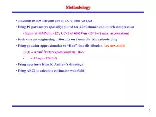
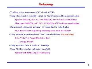
Methodology • Tracking to downstream end of CC-1 with ASTRA • Using PI parameters (possibly) suited for 3.2nC/bunch and bunch compression • Egun @ 40MV/m, -12°; CC-1 @ 60MV/m, -15° (wrt max. acceleration) • Also, egun @40MV/m, -8°; CC-1 @ 20MV/m, -20° (wrt max. acceleration) • Dark current originating uniformly on 16mm dia. Mo cathode plug • Also, dark current originating uniformly from 5mm dia cathode • Using gaussian approximation to “Han” time distribution (see next slide) • I(t) = A*sin2.5(wt)*exp(-B/sin(wt)); B=5 • ~ A*exp(-.5*t2/s2) • Using apertures from R. Andrew’s drawings • Using ABCI to calculate collimator wakefield • Verified with MAFIA by R Wanzenberg
PITZ Dark Current Measurements (Han, et al, EPAC04) Measurements made at screen 1 about 78cm from photocathode old new new “6 times worse than previous rf gun”
FLASH/PITZ Dark Current Measurements Summary (Han, et al, 2006) PITZ 40 – 42 MV/m; dark current measured 78cm from photocathode FLASH
A0 Dark Current Measurements (Hartung, et al, PAC01) Gun @ 35MV/m; dark current measured 45 cm d.s. of gun
Dark Current Time Distribution @ Cathode RF phase (deg)
Dark Current Intensity vs. Distance from Cathode (table) • Egun @ 40MV/m, -8°; CC-1 @ 20MV/m -20° (wrt max. acceleration) • Dark current originating uniformly on 5mm dia. cathode • 10k electrons at photocathode
Dark Current Intensity vs. Distance from Cathode (table) • Egun @ 40MV/m, -12°; CC-1 @ 60MV/m -15° (wrt max. acceleration) • Dark current originating uniformly on 16mm dia. Mo cathode plug • 2K electrons at photocathode
Dark Current Intensity vs. Distance from Cathode (graph) • Egun @ 40MV/m, -12°; CC-1 @ 60MV/m -15° (wrt max. acceleration) • Dark current originating uniformly on 16mm dia. Mo cathode plug
Transverse Wakefield from Collimator (from ABCI) Note: these calculations agree with MAFIA calculations done by R. Wanzenberg gaussian bunch, sz = 1.8mm 1.0 cm dia: peak wake = 750 V/pC/m 1.2 cm dia: peak wake = 520 V/pC/m 1.4 cm dia: peak wake = 370 V/pC/m 1.6 cm dia: peak wake = 270 V/pC/m 1.8 cm dia: peak wake = 200 V/pc/m 2.0 cm dia: peak wake = 160 V/pC/m
Beam Alignment Criteria at the Collimator Limit transverse jitter of downstream beam to < .1sy Dqcoll<20mrad. Using average wake field ~ ½ peak wake field; 3.2 nC; Pbeam=4.7 MeV/c 2 cm dia. collimator: Dyjitter < 380 mm 1 cm dia. collimator: Dyjitter < 80 mm Limit emittance blowup downstream beam to < 10%. De/e = 2*Ds/s < Dx/s Dqcoll less stringent than previous criterion see next 2 slides
Simulation for Offset Dark Current Collimator 20K particles; 1 cm dia. collimator; max. kick = 750 V/pC/m * .001m * 3200 pC / 4.5 MeV = .5 mrad