Medical Imaging Instrumentation & Image Analysis
780 likes | 995 Views
Medical Imaging Instrumentation & Image Analysis. Atam P. Dhawan, Ph.D. Dept. of Electrical & Computer Engineering Dept. of Biomedical Engineering New Jersey Institute of Technology Newark, NJ, 07102 Dhawan@adm.njit.edu. X-rays.

Medical Imaging Instrumentation & Image Analysis
E N D
Presentation Transcript
Medical Imaging Instrumentation & Image Analysis Atam P. Dhawan, Ph.D. Dept. of Electrical & Computer Engineering Dept. of Biomedical Engineering New Jersey Institute of Technology Newark, NJ, 07102 Dhawan@adm.njit.edu
X-rays • X-rays were invented by in Conrad Rontgen in 1895 describing it as new kind of rays which can penetrate almost anything. He described the diagnostic capabilities of X-rays for imaging human body and received the Noble Prize in 1901. • X-ray radiographs are the simplest form of medical imaging through the transmission of X-rays through the body which are then collected on a film. The attenuation or absorption of X-rays is described by the photoelectric and Compton effects providing more attenuation through bones than soft tissues or air.
Transmission Imaging • Not all wavelengths in electromagnetic radiation spectrum are suitable for transmission imaging for human body. • Resolution of the desired image of human body imposes the restrictions on the use of electromagnetic radiation. • There are two important considerations when selecting an electromagnetic radiation for imaging human body: • Resolution: For a useful image, the wavelength must be under 1.0 cm. Higher wavelengths will not provide useful resolution in the image. Wavelength should be shorter than the resolution of interest. • Attenuation: The radiation should be reasonably attenuated when passed through human body. Too much attenuation will result in poor signal-to-noise ratio. If it is completely transmitted, it will not provide any meaningful structural details in the image.
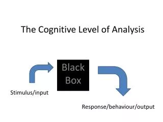
EM Radiation and Imaging • Wave concept of EM radiation explains why it may be reflected, refracted, diffracted, and polarized. • Short EM waves, such as x-rays may react with matter as if they were particles rather than waves. • These particles are actually discrete bundles of energy. • Each bundle of energy is called a quantum or a photon. • Photons travel at the speed of light. • The amount of energy carried by a photon depends on the frequency of the radiation (I.e. number of vibrations per second). • E = hn • E is the photon energy; h is the Planck’s constant = 4.13X10⁻¹⁸ keV sec and n is frequency. • The particle behavior of photon leads to photoelectric effect and Compton scatter.
X-ray Imaging • c=ln or n=c/l • Thus, E= hc/l • where c is velocity of light; hc = 12.4; E is in keV and l is in A. • E = 12.4/l keV • Diagnostic X-ray • 12keV-120keV Transmission 1 - .01 A Wavelength 1 cm 100 m 1 A .0001 A
X-ray Imaging • The diagnostic range of X-rays is used between 1 and around 0.1 A wavelength which corresponds to the photon energy of approximately 12.4 keV to 124 keV. In this range the attenuation is quite reasonable to discriminate bones, soft tissue and air. In addition, the wavelength is short enough for providing excellent resolution of images even with sub mm accuracy. • The diagnostic X-rays wavelength range provides higher energy per photons and provides a refractive index of unity for almost all materials in the body. This guarantees that the diffraction will not distort the image and rays will travel in straight lines. • Shorter wavelengths than diagnostic range of X-rays provides much higher photon energy and therefore less attenuation. Increasing photon energy makes the human body transparent for the loss of any contrast in the image.
X-ray Radiography X-ray Source 3-D Object or Patient Anti-scatter Grid X-ray Screen Film X-ray Screen 2-D Projection Image
3-D Configuration y x m(x,y; z) m15 z m12 m22 Iin(x; y,z) m42 m52 m62 m72 m82 m92 Iout(x; y,z) m11 y x z X-Y Slices
First Generation Scanners Rotate: Angular Scan Translation: Source Translation: Detector
CT Scanner Ring of Detectors Source Rotation Path Source X-rays Object
Magnetic Resonance Imaging Basic Principle: The electromagnetic induction based rf signals are collected through nuclear magnetic resonance from the excited nuclei with magnetic moment and angular momentum present in the body. Most common is proton density imaging.
m N S Spinning Protons Protons with a spinning property behave like small magnets. Spinning around their own axes results in generation of a magnetic moment, m. When placed in external magnetic field, spinning protons align themselves either along or against the external magnetic field. In addition, placing spinning proton in an external magnetic field causes the magnetic moment to precess around an axis parallel to the field direction.
Spinning Proton Protons possessing properties of angular and magnetic moments provide signals for nuclear magnetic resonance Precession Spin
Protons With Random Effect Net Longitudinal Vector: Zero Net Transverse Vector: Zero
Protons Under External Magnetic Field S Higher Energy Level Lower Energy Level w=gH H N
Net Vector Under Thermal Equilibrium Larmor (Precession) Frequency w=gH
Transverse Relaxation Parameter: T2 RF Energy In Phase Zero Net Vector: Random Phase Relaxation
Spin Echo Imaging Sequence RF Energy: 90 Deg Pulse In Phase Zero Net Vector: Random Phase Relaxation Dephasing Rephasing RF Energy: 180 Deg Pulse Echo-Formation
m N J J S Magnetic moment • The spin angular moment, J, and the magnetic moment, m, is described by where g is a gyromagnetic ratio defined in MHz/T. For hydrogen proton g=42.58 MHz/T
Angular Momentum The torque generated by the interaction of magnetic moment of a proton and the external magnetic field is equal to the rate of change of angular momentum and can be given by the equation of motion for isolated spin as
Total Magnetic Moment Assuming N to be the total number of spinning nuclei in the object being imaged, a stationary magnetization vector, can be defined from the available magnetic moments as ,
Rotating Field The transverse magnetization vector in the rotating frame can be written as
Oscillating RF Field Let us assume that H1r and H1 are, respectively, the RF field in the rotating frame and the stationary coordinates systems. An oscillating RF field causing nuclear excitation can be expressed as where
Bloch Equation The relationship between the rates of change of stationary magnetization vector and rotating magnetization vector can then be expressed as During the RF pulse (nuclear excitation phase), the rate of change in the net stationary magnetization vector can be expressed as (the Bloch Equation):
Total Response Considering the total response of the spin system in the presence of an external magnetic field along with the RF pulse for nuclear excitation followed by the nuclear relaxation phase, the change of the net magnetization vector can be expressed as where is the net magnetization vector in thermal equilibrium in the presence of an external magnetic field H0 only, and T1and T2 are, respectively, the longitudinal (spin-lattice) and transverse (spin-spin) relaxation times in the nuclear relaxation phase when excited nuclei return to their thermal equilibrium state.
Relaxation Process represents the initial transverse magnetization vector with the time set to zero at the end of the RF pulse of duration tp.
Mx,y (t) t Mz (t) t Relaxation Vectors
Gradient Coils Gradient Coils RF Coils Magnet Patient Platform Data-Acquisition System Monitor COMPUTER MR Imaging
Spin-Echo Imaging Sequence Slice-Selection Z-direction z
TE /2 180 deg RF pulse 90 deg RF pulse RF pulse Transmitter Gz: Slice Selection Frequency Encoding Gradient TE /2 Gx: Phase Encoding Gradient Gy: Readout Frequency Encoding Gradient TE NMR RF FID Signal Imaging Through MR: Spin Echo
90 deg RF pulse 90 deg RF pulse RF pulse Transmitter Gz: Slice Selection Frequency Encoding Gradient 2t 2t t 2t 2t Gx: Oscillating Gradient 2t 2t 2t 2t Gy: Readout Gradient NMR RF FID Signal MR Imaging: Single Shot EPI
T1 and T2 Contrast Typical NMR Tissue Values at 0.15 T
MR Images T2 Weighted Spin Density Image T1 Weighted
Sagital y z y Axial y z x x Coronal x z 3-D Imaging
MRI • There are several imaging modalities within MRI. • T1 and T2 weighted images • Spin Echo and multiple echo sequence images • MR Spectroscopy • Blood flow imaging • Perfusion imaging • Function imaging
MRI Advantage • The most important advantage of the MRI is its ability to provide unprecedented contrasts between various organs and tissues and the three-dimensional nature of imaging methods. • Selective 3-D imaging is provided by appropriate selection of gradient fields and phase encoding methods. • A variety of contrast images can be created by different combinations of weighting of T1, T2 and echo images • MR spectroscopy provides a great potential for meaningful tissue characterization. • Functional MRI holds great promise for the future.