Download
1 / 23
230 likes | 398 Views
A Single-Pass Cache Simulation Methodology for Two-level Unified Caches. Wei Zang and Ann Gordon-Ross + University of Florida Department of Electrical and Computer Engineering. + Also affiliated with NSF Center for High-Performance Reconfigurable Computing .

E N D
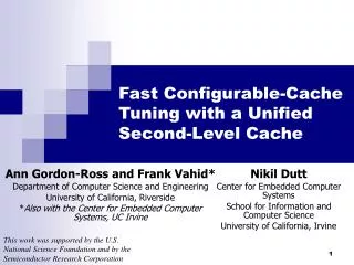
A Single-Pass Cache Simulation Methodology for Two-level Unified Caches Wei Zang and Ann Gordon-Ross+ University of FloridaDepartment of Electrical and Computer Engineering + Also affiliated with NSF Center for High-Performance Reconfigurable Computing This work was supported by the National Science Foundation (CNS-0953447) and (ECCS-0901706)
Introduction • Caches are a good candidate for system performance and energy optimization • Different applications have vastly different cache requirements • Configurable cache parameters: total size, line size, associativity • Cache tuning • Determine appropriate cache parameters (cache configuration) to meet optimization goals • Difficult to determine the best cache configuration given very large design spaces for highly configurable caches associativity size line size
…very time consuming (setup and simulation time)… Instruction Set Simulator . . . . . . Simulation-Based Cache Tuning • Cache tuning at design time via simulation • Performed by the designer • Typically iterative simulation using exhaustive or heuristic methods Miss rate with c1 Simulating withc1 Miss rate with c2 Simulating withc2 Embedded Application Best c3 for optimization goals Miss rate with c3 Simulating withc3 . . . C1,C2,C3,…,Cnare the n cache configurations in design space Simulating withcn Miss rate with cn
Miss rate with c1 Miss rate withc2 Miss rate withc3 . . . Miss rate withcn Single-Pass Cache Tuning • Simultaneouslyevaluate multiple cache configurations during one execution • Trace-driven cache simulation • Use memory reference trace Generate trace file via a singlefunctional simulation Single-pass trace-driven cache simulation Embedded Application Best c3 for optimization goals . . . Speedup simulation time
Previous Works on Single-Pass Simulation • Stack-based algorithm • Stack data structure stores access trace • Simple data structures, amenable to hardware implementation • Tree-based algorithm • Decreased simulation time • Complex data structures, more storage requirements • Limitation . . . . . . U-SPaCS T-SPaCS (Zang and Gordon-Ross, 11) Popular Main Mem Main Mem Main Mem L2 U cache L2 D cache L2 I cache L1 cache L1 I cache L1 D cache L1 I cache L1 D cache Processor Processor Processor
Single-level Cache Simulation • Stack-based single-pass trace-driven cache simulation for single-level caches One cache configuration in design space: block size = 4 (22), number of cache sets = 8 (23) Processing address Trace addresses (001) 11110 Stack 010 11110 Search stack 110 10100 (001) 11110 010 11110 No previous access in stack 111 11101 110 10100 101 01000 111 11101 010 11110 101 01000 Compulsory miss 001 11110 010 11110 Stack update 001 11110 Block offset tag Index
Single-level Cache Simulation • Stack-based single-pass trace-driven cache simulation for single-level caches One cache configuration in design space: block size = 4 (22), number of cache sets = 8 (23) Processing address Trace addresses (010) 11110 Stack 010 11110 Search stack 110 10100 (001) 11110 (010) 11110 010 11110 No previous access in stack 111 11101 110 10100 101 01000 111 11101 010 11110 101 01000 Compulsory miss 010 11110 001 11110 Stack update Block offset tag Index
Single-level Cache Simulation • Stack-based single-pass trace-driven cache simulation for single-level caches One cache configuration in design space: block size = 4 (22), number of cache sets = 8 (23) Processing address Trace addresses (101) 01000 Stack 010 11110 Search stack 110 10100 (010) 11110 (101) 01000 010 11110 No previous access in stack 111 11101 (001) 11110 110 10100 101 01000 111 11101 101 01000 Compulsory miss 010 11110 001 11110 Stack update Block offset tag Index
Single-level Cache Simulation • Stack-based single-pass trace-driven cache simulation for single-level caches One cache configuration in design space: block size = 4 (22), number of cache sets = 8 (23) Processing address Trace addresses (111) 11101 Stack 010 11110 Search stack 110 10100 (111) 11101 (101) 01000 010 11110 No previous access in stack 111 11101 (010) 11110 110 10100 (001) 11110 111 11101 101 01000 Compulsory miss 010 11110 001 11110 Stack update Block offset tag Index
Single-level Cache Simulation • Stack-based single-pass trace-driven cache simulation for single-level caches One cache configuration in design space: block size = 4 (22), number of cache sets = 8 (23) Processing address Trace addresses (110) 10100 Stack 010 11110 Search stack 110 10100 (111) 11101 (110) 10100 010 11110 No previous access in stack (101) 01000 110 10100 (010) 11110 111 11101 (001) 11110 101 01000 Compulsory miss 010 11110 001 11110 Stack update Block offset tag Index
Single-level Cache Simulation • Stack-based single-pass trace-driven cache simulation for single-level caches One cache configuration in design space: block size = 4 (22), number of cache sets = 8 (23) Processing address Trace addresses Stack 010 11110 (010) 11110 Search stack (110) 10100 same block Stack update 010 11110 (111) 11101 (111) 11101 Conflicts: blocks that map to the same cache set as processed address Conflict evaluation: determine the config. that results in a hit 110 10100 (101) 01000 111 11101 (010) 11110 (010) 11110 101 01000 (001) 11110 010 11110 Conflicts # = 1 cache associativity >= 2, hit 001 11110 Block offset tag Index
Challenges in Unified L2 Cache Analysis • U-SPaCS targets exclusive hierarchy • Storage space and simulation time efficiency (T-SPaCS) • L1 instruction (I) and data (D) caches share L2 cache-> introduces interference in the unified (U) L2 cache • M L1 I cache configurations and N L1 D cache configurations generates M∙N unique eviction orderings • Efficiently maintain and process the orderings for large design space Depends on relative eviction ordering of the two L1 caches Interdependency
U-SPaCS Overview Access trace file Execute application T[N] : T[t] : T[3] T[2] T[1] L1 I cache config. L1 miss L2 analysis L2 analysis L1 analysis Stack update Instruction T[t] L2 U cache config. Data T[t] Accumulated L1 I & D cache misses L2 cache misses & write-backs for all cache config. L1 analysis L2 analysis L2 analysis Stack update L1 miss L1 D cache config. B: block size U-SPaCS
Eviction Order Recording • L2 cache storage depends on relative eviction ordering • Stack maintains cache access ordering of unique addresses • Not sufficient to determine eviction ordering • Explicitly record eviction ordering Instruction (data) stack For each c1_inst(c1_data) Eviction time array Block address X E: The time when X is evicted from L1 I (D) cache with L1 config. c1_inst(c1_data) E=‘0’: X is still in L1, not evicted yet Process block address A: L2 analysis A’s S2 conflicts that are evicted to L2 later than old A’s eviction (E of conflicts >E of A) determine A’s L2 hit/miss c1_inst: L1 I cache configuration • c1_data: L1 D cache configuration S2: # of sets in L2 cache
U-SPaCS Processing Example I4(110) I1(010) D2(010) D2(010) I4(110) I1(010) D3(010) I2(110) I2(110) I1(010) I1(010) D1(010) D1(010) I3(010) I3(010) D3(010) Trace 5 8 7 4 6 3 2 1 I Stack D Stack I1(010) -> 0 -> 0 I4(110) I3(010) -> 0 I2(110) -> 0 -> 0 -> 0 D3(010) D1(010) -> 0 D2(010) -> 0 -> 7 -> 5 -> 4 -> 6 -> 8 Trace order 2: Process I1(010) Compulsory miss Trace order 1: Process D1(010) Compulsory miss Trace order 3: Process I2(110) Compulsory miss Conflicts for S1: I1(010) W1 = 2, no eviction Trace order 4: Process I3(010) Compulsory miss Conflicts for S1: I2(110) I1(010) W1 = 2, I1(010) is evicted Trace order 5: Process D2(010) Compulsory miss Conflicts for S1: D1(010) W1 = 1, D1(010) is evicted Trace order 8: Process I1(010) Trace order 6: Process I4(110) Compulsory miss Conflicts for S1: I3(010) I2(110) I1(010) W1 = 2, I2(110) is evicted Trace order 7: Process D3(010) Compulsory miss Conflicts for S1: D2(010) D1(010) W1 = 1, D2(110) is evicted Conflicts for S1: I4(110) I3(010) I2(110) W1 = 2, L1 miss, I3(010) is evicted Eviction time > 4 W2 = 2, L2 miss Conflicts for S2: From I Stack: I3(010)->0 From D Stack: D3(010)->0 D2(010)->7; D1(010)->5 Eviction time of I1(010) is 4
Special Case - Occupied Blank Labeling I5 I5 I6 I6 I2 I2 I3 I1 I1 I4 I4 I5 I2 I2 I7 I7 I3 I5 Trace 1 4 3 2 5 9 8 6 7 BLK Access I2 S1 < S2 Hit in L2 I5 I Stack -> 0 -> 0 -> 0 -> 0 -> 0 -> 0 I3 -> 0 -> 0 -> 0 I4 I7 I5 I6 I2 I1 Access I5 Occupied blank (invalid due to exclusive) (fetching I2 evicts I6 that maps to a different L2 set) • From cache: miss in L1/L2 • Analysis from Stack: -> 8 -> 7 -> 6 -> 9 -> 4 -> 3 -> 5 Conflicts for S2 : I2->0 I1->7 I3->5 I4->4 (no conflicts in D Stack) I5->3 Eviction time > 3; L2 hit Inaccurate! L2 conflicts should count BLK Solution: occupied blank labeling
Data Address Processing • Similar to instruction address processing • Additional dirty data write-back counting • Writing a dirty cache block avoids previous writing to memory • #of write-back = # of total writes - # of write avoids • For each c_hier(c1_inst, c1_data, c2) ‘1’: dirty; ‘0’: clear D stack Bit array for dirty status indication D1 Now process D4, during stack update: Remove the old D4, and push new D4 on top D2 D4 is a write: Bit array of old D4 D3 D4 D5 Bit array of new D4 (All dirty) c_hier: cache hierarchy configuration c1_inst: L1 I cache configuration • c1_data: L1 D cache configuration c2: L2 cache configuration
Data Address Processing • Similar to instruction address processing • Additional dirty data write-back counting • Writing a dirty cache block avoids previous writing to memory • #of write-back = # of total writes - # of write avoids • For each c_hier(c1_inst, c1_data, c2) ‘1’: dirty; ‘0’: clear D stack Bit array for dirty status indication D1 Now process D4, during stack update: Remove the old D4, and push new D4 on top D2 D4 is a read: Bit array of old D4 D3 D4 D5 This c_hier results in L2 miss Bit array of new D4 c_hier: cache hierarchy configuration c1_inst: L1 I cache configuration • c1_data: L1 D cache configuration c2: L2 cache configuration
Experiment Setup • Design space • L1 I & D caches: cache size (2k8k B); block size (16B64B); associativity (direct-mapped4-way) • L2 cache: cache size (16k64k B); block size (16B64B); associativity (direct-mapped4-way) • 2,187 configurations • 24 benchmarks from EEMBC, Powerstone, and MediaBench • ModifSimpleScalar’s‘sim-fast’ to generate cache access traces • Implement U-SPaCS in C • Modify ‘Dinero’ to simulate exclusive hierarchy cache • Produces the exact miss and write-back rates for comparison U-SPaCS results are 100% accurate for all configurations! Cache tuning using U-SPaCS determines optimal cache configuration!
Simulation Time Efficiency • U-SPaCS’s (single-pass evaluation) vs. Dinero’s (iterative evaluation) simulation times for entire design space Max 72X Avg 41X
Analysis of Speedup Variation Linearly increase Variation Dinero simulation time (s) U-SPaCS simulation time (s) U-SPaCS speedup
Analysis of Speedup Variation Outlier High average L1 cache miss rate Product of the average L1 cache miss rate and the average stack size High importance placed on L1 cache miss rate All benchmarks follow decreasing tread Product of the square of the average L1 cache miss rate and the average stack size
Conclusions • U-SPaCS simulates an exclusive two-level cache hierarchy with a unified L2 cache in a single pass • U-SPaCS’s cache miss rates and write-back rates are 100% accurate for all cache configurations • U-SPaCSachieves an average 41X simulation time speedup as compared to iterative simulation • Our ongoing work • Extend U-SPaCS to support multi-core architectures • Implement U-SPaCS in hardware for dynamic cache tuning