Download
1 / 18
180 likes | 422 Views
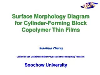
Surface Morphology Diagram for Cylinder-Forming Block Copolymer Thin Films Xiaohua Zhang. Center for Soft Condensed Matter Physics and Interdisciplinary Research. Soochow University. A. B. Background. Phase diagram for a block copolymer with various structures. Current Solutions.

E N D
Surface Morphology Diagram for Cylinder-Forming Block Copolymer Thin Films Xiaohua Zhang Center for Soft Condensed Matter Physics and Interdisciplinary Research Soochow University
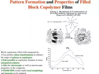
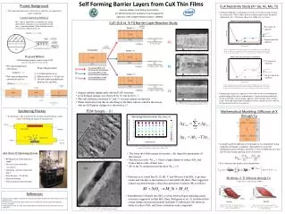
A B Background Phase diagram for a block copolymer with various structures Current Solutions Orientation of Cylinders • Needs • - 3D nanostructure Manufacturing • - 3D characterization of nanostructure • - Control of 3D nanostructure • Current Problems • - 2D structures • - Physical Template 200 nm 200 nm T. Russell et al Langmuir, 2008, 24, 3545 Y. Gong et al Macromolecules 2006 39, 3369 T. Russell et al Adv. Mater. 2004 16, 226
O2 RIE O2 RIE CF4RIE CF4RIE 35 nm period Hitachi Global Storage Technologies Self-assembling Materials for Bottom-up Nanofabrication Processes • Challenges • Contain defects in many self assembled nanostructures. • Lack sufficient long-range order for certain nanotechnology applications. J. Cheng, Nature Materials, 3, 823-828(2004)
Assembly of Block Copolymer Films • Our goal: • Develop critical measurement solutions that enable nanomanufacturing with guided block copolymer assembly for next generation magnetic data storage, nanoscale electronics, and high efficiency membranes for energy. • Method: • Combine unique modeling platforms with precision thermal processing techniques to enable the development of small angle x-ray and neutron scattering to measure structural uniformity, including orientation distributions, and pattern placement in self-assembled polymer films within templated surfaces. • Controlling Orientation using • Cold Zone Annealing (CZA), sample preparation procedure and unique thermal processing technique • Metrology of Orientation in Nanostructured Films • 3D Nanostructure for Cylinder-Forming Block Copolymer Thin Films
200nm Flow Coating without Residual Solvent Flow Coating Spin Coating 3D Nanostructure Surface Morphology Diagram of PS-PMMA Block Copolymer Films on Oxide Silicon Substrate Materials: Poly (styrene-block-methyl methacrylate) Mn: PS(35500)-PMMA(12200) Mw/Mn: 1.04 C. M Stafford et al.Rev. Sci. Instr. 11(2006) 023908-1
Sample Preparation Procedure Dependence 200nm Spin-coated in air Flow-coated in air Spin-coated in toluene vapor Spin-coated in toluene vapor & prebaked prior to annealing Film thickness: 120 nm Annealing: 155˚C for 15 h Prebaking: 93 ˚C for 15 h
200nm 58nm 71nm 86nm 104nm 130nm 168nm PMMA PS s Increasing Film Thickness AFM phase images of flow coated PS-b-PMMA block copolymers after annealing at 147 ˚C for 15 h.
θ θ qx Detector qz θ θ 3D Characterization of Nanostructure by Neutron Reflectivity (NR) NCNR in NIST Incidentneutrons 2θ Sample
200nm Air Si dPS-b-PMMA, 80 nm, 147 oC for 15 h
We convert from beam-coordinates (qx,qy,qz) to sample-coordinates (Qx,Qy,Qz) using a rotation matrix Orientation Distribution Measurement of 3D Nanostructure by RSANS Qz Qy Qx
Samples show a mix of parallel and perpendicular cylinder scattering Low-q scattering from size disorder Hexagonal pattern from laying-down cylinders Weak ring from random component Scattering peak from standing-up cylinders
200nm Film thickness:136nm Annealing:147ºC for 15h Content of perpendicular cylinders:80% Film thickness:141nm Annealing:165ºC for 15h Content of perpendicular cylinders:59% Data was fit by extending the model of Ruland and Smarsly. Ruland, W.; Smarsly, B. J. Appl. Cryst. 2005,38, 78-86.
12% Residual Solvent 16% Residual Solvent Self-assembly Driving Force of 3D Nanostructure NR Measurements on Residual Solvent in PS-b-PMMA Films PS-b-PMMA in deuterated toluene
PMMA Films NR data (symbols) of as-cast, one-step (93 oC for 15 h) and two-step (93 oC for 15 h followed by 155 oC for another 15 h) annealed PMMA films with as-cast film thickness of 121 nm at fixed molecular weight (20 kg/mol). NR scans (symbols) measured from the PMMA films of different thickness at fixed molecular weight (20 kg/mol).
FTIR Characterization of Residual Solvent in BCP Films Macromolecules2010, 43, 1117–1123. ACS Nano, 2008, 2, 2331-2341. PS (51kg/mol) PMMA (20kg/mol) Film thickness : 160 nm. The estimation of residual d-toluene concentration is based on its characteristic peak located around 2274 cm-1. Calibration is made with the area ratio of the strong bands corresponding to d-toluene (2274 cm-1) and PMMA (1730 cm-1) in the FTIR spectra of 3% polymer solution.
Film preparation procedure, and other processing effects, cannot be ignored in nanomanufacturing applications. Fundamentally demonstrate the interplay between intrinsic BCP structure and processing conditions. R-SANS and NR can deduce orientational distribution in BCP cylinder thin films. Summary